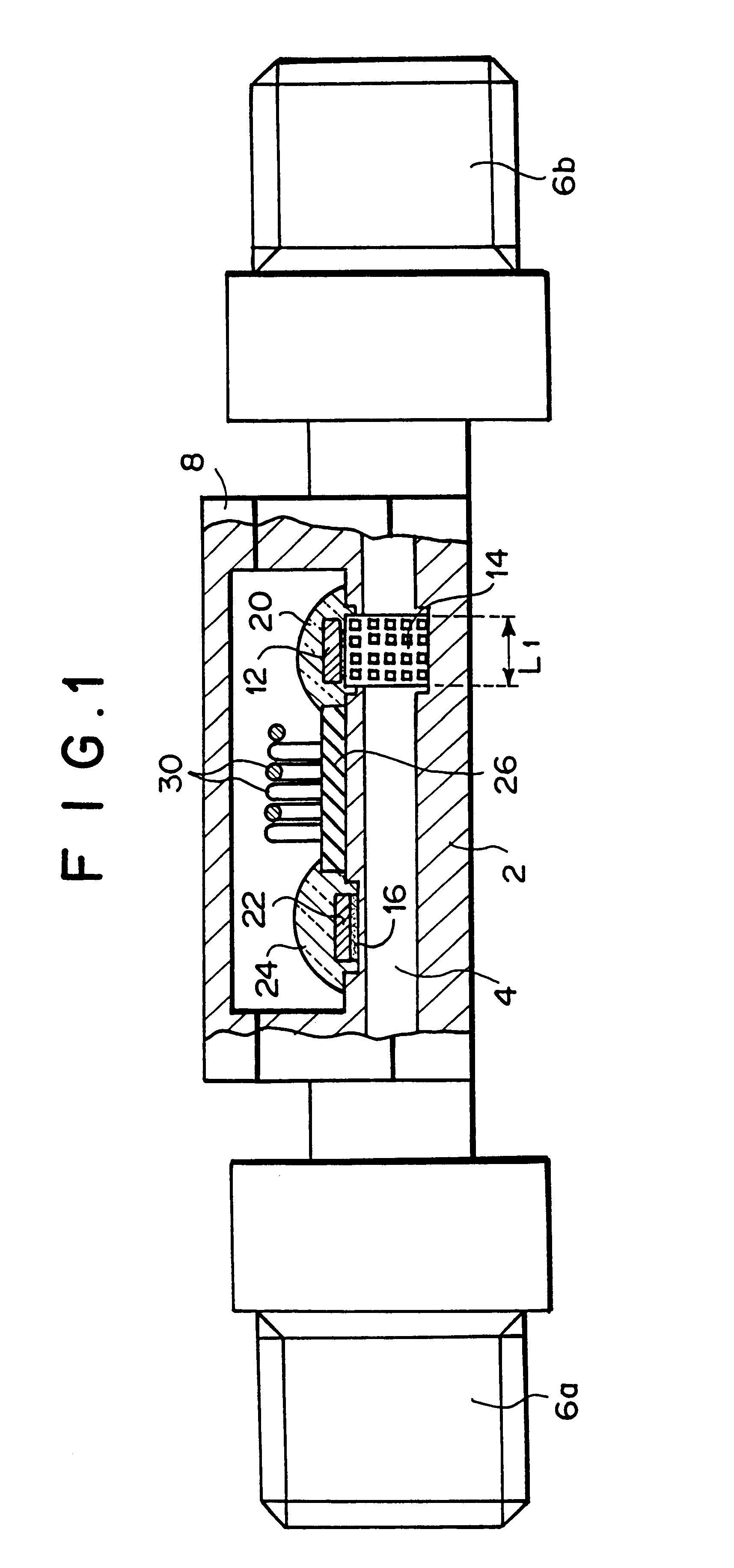
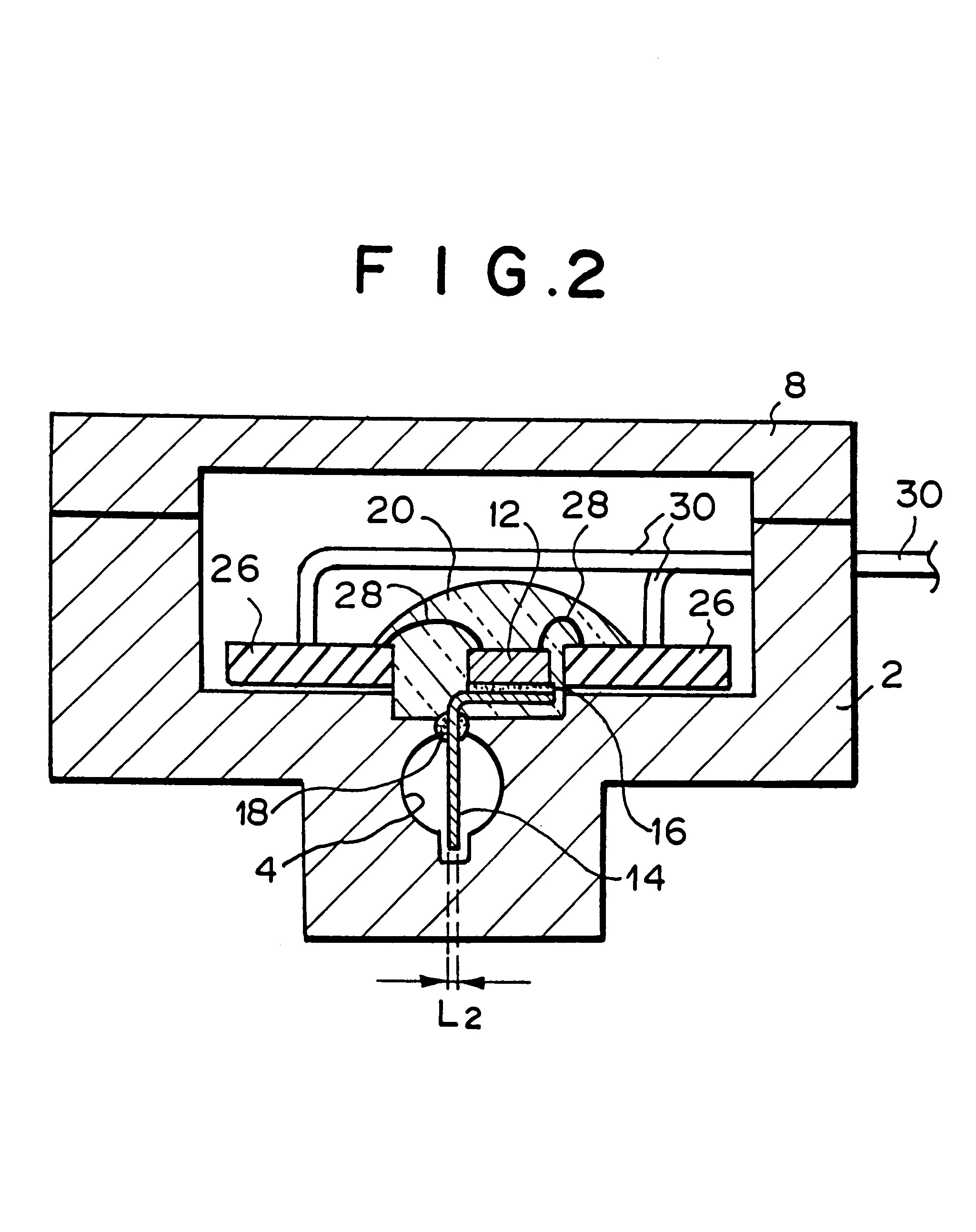
Flow rate sensor, flow meter, and discharge rate control apparatus for liquid discharge machines
a flow rate sensor and flow meter technology, applied in lighting and heating apparatus, liquid/fluent solid measurement, instruments, etc., can solve the problems of fluid extinguishing, difficult to accurately measure the flow rate of fluid, and large temperature increas
- Summary
- Abstract
- Description
- Claims
- Application Information
AI Technical Summary
Benefits of technology
Problems solved by technology
Method used
Image
Examples
first embodiment
FIG. 23 is a schematic diagram showing a discharge amount control appatatus of liquid discharging equipment according to the present invention. In this embodiment, a non return type nozzle is used as the liquid discharge equipment, and fuel oil such as kerosene or the like is used as liquid to be supplied to or discharged from the nozzle.
In FIG. 23, 51 represents a fuel oil tank serving as a liquid supply source. The tank is connected to one end of a pipe line 52, and a non return type nozzle 53 is connected to the other end of the pipe line 52. The nozzle 53 constitutes a non return type hydraulic oil burner having an air supply nozzle, ignition means, etc. A pump (P) 54 and a flow rate adjusting valve (V) 55 are disposed at some midpoint of the pipe line 52, and a flow rate sensor (S) 56 is disposed between the flow rate adjusting valve 55 and the nozzle 53. A displacement type pump may be used as the pump 53, and the discharge amount thereof may be variable.
57 represents a contro...
second embodiment
FIG. 24 is a schematic diagram showing the discharge amount control apparatus for liquid discharge equipment according to the present invention. In FIG. 24, the elements having the same functions as FIG. 23 are represented by the same reference numerals.
In this embodiment, the pipe line 52 which is the same as that of the first embodiment is provided with a return passage 58 for returning the fuel oil from the just upstream position of the flow rate sensor 56 (that is, the position between the flow rate adjusting valve 55 and the flow rate sensor 56) to the upstream position of the pump 54. A check valve (v) 59 is interposed in the return passage 58. The check valve 59 passes liquid therethrough (return the fuel oil to the upstream side of the pump 54) when the pressure difference is above a predetermined value, and it can prevent abnormal pressure increase in the pipe line 52 between the pump 54 and the flow rate sensor 56.
The minimum pressure difference for allowing the pass of th...
third embodiment
FIG. 25 is a schematic diagram showing the discharge amount control apparatus for liquid discharge equipment according to the present invention. In FIG. 25, the elements having the same functions as FIGS. 23 and 24 are represented by the same reference numerals.
In this embodiment, a return nozzle is used as the liquid discharge equipment, and fuel oil such as kerosene or the like is used as the liquid to be supplied to and discharged from the nozzle.
In this embodiment, the pipe line 52 is connected to the fuel oil supply end of a return nozzle 53'. The nozzle 53' constitutes a return type hydraulic oil burner having an air supply nozzle, ignition means, etc. A first flow rate sensor (Si) 56' is secured to the pipe line 52 between the flow rate adjusting valve 55 and the nozzle 53'.
Further, one end of a return pipe 60 is connected to the fuel oil return end of the return type nozzle 53', and the other end of the return pipe 60 is connected to the pipe line 52 at the upstream side of ...
PUM
 Abstract
Description
Claims
Application Information
 - R&D
- Intellectual Property
- Life Sciences
- Materials
- Tech Scout
- Unparalleled Data Quality
- Higher Quality Content
- 60% Fewer Hallucinations
Browse by: Latest US Patents, China's latest patents, Technical Efficacy Thesaurus, Application Domain, Technology Topic, Popular Technical Reports.
© 2025 PatSnap. All rights reserved.Legal|Privacy policy|Modern Slavery Act Transparency Statement|Sitemap|About US| Contact US: help@patsnap.com


