Continuously variable transmission

a transmission line and continuous technology, applied in the field of pulleys, can solve the problems of inability to stand for long periods of use, inability to reliably connect the liners to the annular main sections of the respective flanges, and inability to use for a long tim

Inactive Publication Date: 2003-11-18
SCHAEFFLER TECH AG & CO KG
View PDF6 Cites 31 Cited by
  • Summary
  • Abstract
  • Description
  • Claims
  • Application Information

AI Technical Summary

Benefits of technology

An object of the instant invention is to provide a pulley wherein the liners are

Problems solved by technology

The aforementioned composite flanges exhibit the drawback that the direct connections between the liners and the annular main sections of the respective flanges are unreliable and can stand only relatively

Method used


Image

  • Continuously variable transmission
  • Continuously variable transmission
  • Continuously variable transmission

Examples


Embodiment Construction

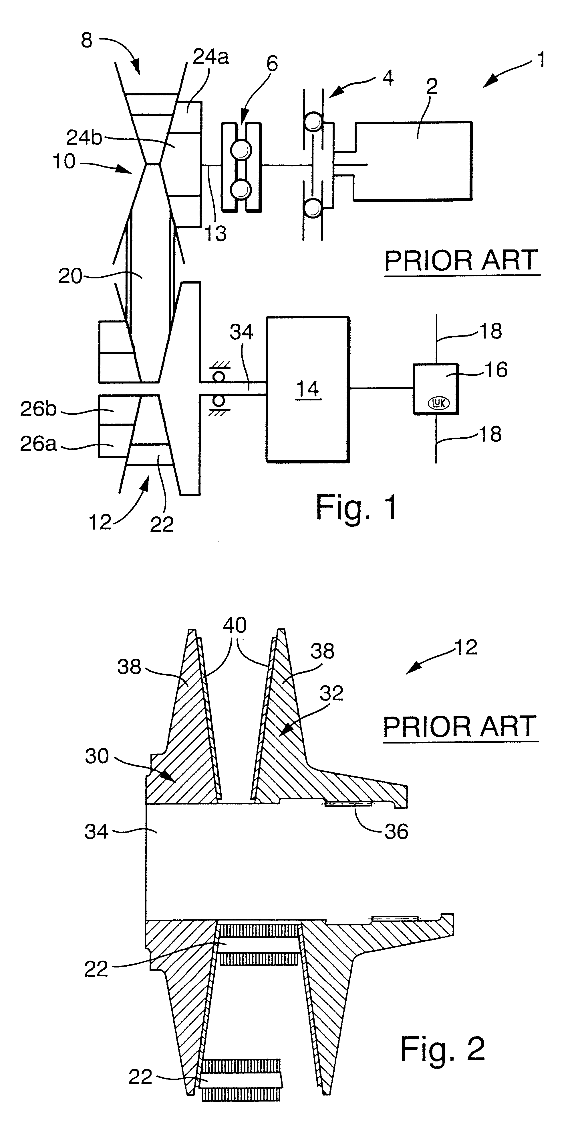
FIG. 1 shows certain details of a power train 1 which is of the type shown and described in the aforementioned published German patent application Serial No. 197 48 675 A1 and can be utilized in a motor vehicle to transmit torque between a prime mover 2 (such as an internal combustion engine, an electric motor or a hybrid prime mover) and the wheels (not shown) of the vehicle. The rotary output element (e.g., a crankshaft or a camshaft) of the prime mover 2 can transmit torque to a torsional vibration damper 4 which, in turn, can transmit torque to a torque sensor 6. The components 4, 6 can be of the type described, for example, in the aforementioned U.S. Pat. No. 5,711,730 to Friedmann et al. The torque sensor 6 is mounted on the input shaft 13 of a continuously variable transmission (CVT) 10, the output shaft 34 (see also FIG. 2) of which can transmit torque to a torque transmitting unit 14 normally comprising a starter element (such as a clutch or a converter) and a device which ...


PUM


Abstract

An adjustable pulley for use in a continuously variable transmission has two coaxial flanges at least one of which is a composite flange having an annular main section with a conical surface adjacent a reinforcing liner of wear resistant material. The liner is secured to the main section of the composite flange by a one-piece or composite disc-shaped insert one side of which has several portions affixed (such as bonded and/or riveted) to the adjacent side of the liner, and the other side of which has several portions affixed to the conical surface and/or another part of the main section. Those portions of the one side of the insert which are affixed to the liner are out of register with those portions of the other side of the insert which are affixed to the main section to thus enable the liner to move relative to the conical surface in one or more directions other than circumferentially of the main section.

Description

The invention relates to transmissions in general, and more particularly to transmissions which employ pulleys or sheaves. Still more particularly, the invention relates to improvements in pulleys of the type wherein two coaxial flanges have confronting surfaces engageable with a portion of an endless flexible element (such as a belt or a chain) which transmits torque to or receives torque from the pulley. Pulleys of the type to which the present invention pertains can be utilized with particular advantage in transmissions of the type known as CVT (continuously variable transmissions), e.g., in the power trains of motor vehicles to directly or indirectly transmit torque between a prime mover (such as an internal combustion engine) and the wheels of the motor vehicle. Reference may be had, for example, to commonly owned U.S. Pat. No. 5,667,448 (granted Sep. 16, 1997 to Oswald FRIEDMANN for "POWER TRAIN"), to commonly owned U.S. Pat. No. 5,711,730 (granted Jan. 27, 1998 to Oswald FRIE...

Claims


Application Information

Patent Timeline
IPC IPC(8): F16H55/56F16H55/32F16H55/46
CPCF16H55/56
Inventor FISCHER, ROBERTWALTER, BERNHARDBAUER, CHRISTIANFRIEDMANN, OSWALD
Owner SCHAEFFLER TECH AG & CO KG
Why Eureka
Try Eureka