Latched active fail-safe circuit for protecting a differential receiver

a failsafe circuit and differential receiver technology, applied in the field of differential receivers, can solve the problems of large signal swing, increased system noise, and reduced data quality and transmission rate, and achieve the effects of increasing electro-magnetic interference (emi) and system nois

Inactive Publication Date: 2003-11-18
DIODES INC
View PDF12 Cites 41 Cited by
  • Summary
  • Abstract
  • Description
  • Claims
  • Application Information

AI Technical Summary

Problems solved by technology

Although the cables may be only a few meters in length, a transmission-line effect degrades data quality and transmission rate.
Large signal swings also increases electro-magnetic interference (EMI) and system noise.
However, the voltage difference across the terminating resistor between the two signals is small, perhaps only a few hundred millivolts.
The transmitter can also fail or be in a high-impedance output state.
False triggering of receiver logic can occur.
Thus using pullup and pulldown resistors are not effective with LVDS receivers, which use 100-Ohm terminating resistors.
Unfortunately, the addition of series resistors 24, 26 increases the R-C delay of the cable d

Method used


Image

  • Latched active fail-safe circuit for protecting a differential receiver
  • Latched active fail-safe circuit for protecting a differential receiver
  • Latched active fail-safe circuit for protecting a differential receiver

Examples


Embodiment Construction

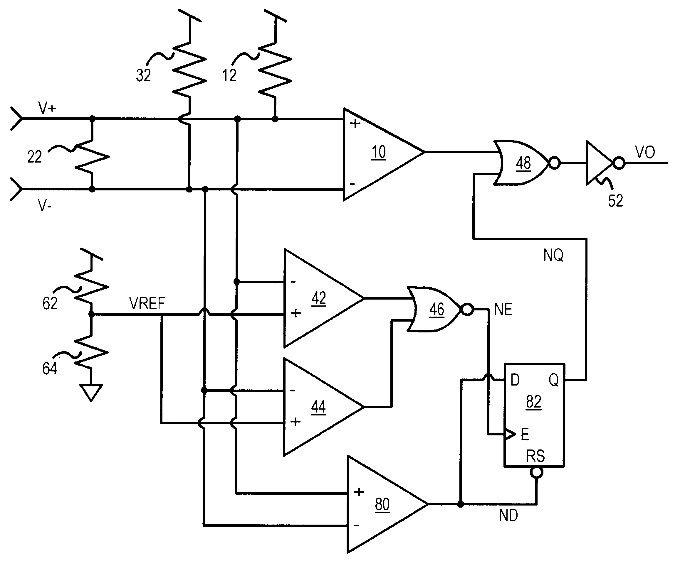
Several other embodiments are contemplated by the inventor. For example reference voltage VREF can be lowered somewhat, such as to 95% or less of the Vcc, when a narrower common-mode range is expected. Many different resistance values can be used, and the load or terminating resistor is normally selected to match the impedance of the V+, V- transmission lines, usually in the range of 50 to 120 Ohms. The offset can be less than or more than 50 mV, such as 20 mV.

Various inversions in the logic can be introduced, and NAND gates rather than NOR gates can be substituted using DeMorgan's theorem. The inverting and non-inverting inputs to the comparators and the differential amplifier can be swapped to invert their outputs. Active-low signals rather than active-high signals can be substituted. Several gates can be combined into a larger gate, such as a 3-input AND or NAND gate. The overall output can sometimes be disabled by turning off the differential amplifier with the fail-safe signal ...


PUM


Abstract

A fail-safe circuit for a differential receiver can tolerate noise. A latch is enabled when both differential inputs V+, V- rise above a reference voltage that is close to Vcc. The latch, once enabled, is set by an offset amplifier, signaling the fail-safe condition. The offset amplifier sets the latch when V+ is above or equal to V-. The differential amplifier has a small offset voltage to allow the latch to remain set when V+ and V- are equal in voltage. An output from a differential amplifier receiving V+ and V- can be blocked by a gate when the fail-safe condition is latched. Pullup resistors pull V+, V- to Vcc when an open failure occurs. The latch remains set when common-mode noise occurs on V+, V-, preventing noise from prematurely disabling the fail-safe condition. Such noise coupled into a broken cable is usually common-mode.

Description

BACKGROUND OF INVENTIONThis invention relates to differential receivers, and more particularly to latched fail-safe circuits for low-voltage differential signaling (LVDS) receivers.Networking equipment and other electronic systems often transmit signals over cables. Although the cables may be only a few meters in length, a transmission-line effect degrades data quality and transmission rate. Large signal swings also increases electro-magnetic interference (EMI) and system noise. To send signals over these cables, special drivers and receivers have been developed.The problems of the transmission-line effect have been mitigated with reduced voltage swings. Also, a pair of physical signals driven to opposite states are together used to transmit a single logical signal. Such differential signaling has been used with Emitter-coupled logic (ECL) for many years, and more recently in low-voltage differential signaling (LVDS) drivers and receivers.LVDS drivers have a pair of outputs that are...

Claims


Application Information

Patent Timeline
IPC IPC(8): H03K5/125H03K19/007H03K5/1252H04L25/08
CPCH03K5/1252H04L25/085H03K19/007
Inventor WONG, ANTHONY YAP
Owner DIODES INC
Why Eureka
Try Eureka