
Cleat assembly for trash compactor vehicle wheels

a technology for trash compactors and cleat bases, which is applied in the direction of roads, construction, foundation engineering, etc., can solve the problems of increasing the cost of additional pins, prolonging the usable life of trash compactor vehicle wheels and cleat bases, and avoiding the use of hammers to drive pins out of position

Inactive Publication Date: 2003-11-25
BIERWITH ROBERT S
View PDF27 Cites 19 Cited by
  • Summary
  • Abstract
  • Description
  • Claims
  • Application Information

AI Technical Summary

Benefits of technology

Accordingly, the present invention provides a cleat assembly that is ideally suited for use on a trash compactor vehicle wheel. The connection system of the cleat assembly is easy to fabricate and, since it preferably extends within the width of the receiving portion of the cleat base, no abrasive material can enter the interface between the replaceable cleat and the cleat base over which it extends. The locking portion of the connection system fully engages the replaceable cleat and the cleat base, with the interference section fully engaging the cleat interference portion of the replaceable cleat, thus providing a tight wedge lock fit and helping prevent relative motion between the replaceable cleat and its associated cleat base.
A connection system of a cleat assembly in accordance with the present invention is reusable, thereby eliminating pin replacement. Such an elimination helps reduce the expense for each cleat exchange. Furthermore, a connection system of a cleat assembly in accordance with the present invention is easily removable without use of a hammer, thereby reducing the possibility of any injuries when exchanging (i.e., replacing) cleats.

Problems solved by technology

As a result, only the replaceable cleat normally needs (and allows) replacement, thus prolonging the usable life of the trash compactor vehicle wheel and cleat base.
The requirement of additional pins increases expense.
Use of a hammer to drive the pin out of position is also undesirable, since it imposes a danger of bodily injury caused by flying chips from the pin or other parts, or from flying dirt, debris, sand, dust, etc.
Further, in conventional cleat assemblies for trash compactor vehicle wheels, the interface between the replaceable cleat and its cleat base can be inadequately sealed.
Thus, dirt, sand, grit and other abrasive material can enter the interface and slowly grind or wear the replaceable cleat and cleat base, leading to premature failure.

Method used


Image

  • Cleat assembly for trash compactor vehicle wheels
  • Cleat assembly for trash compactor vehicle wheels
  • Cleat assembly for trash compactor vehicle wheels

Examples


Embodiment Construction

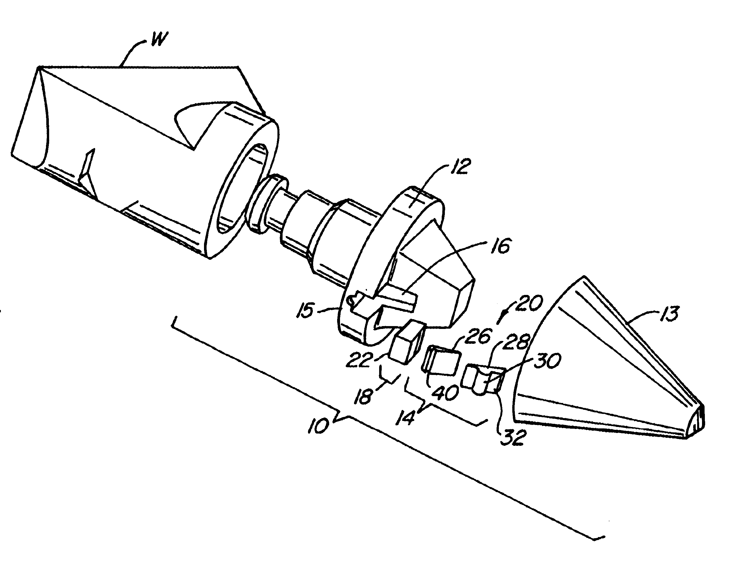
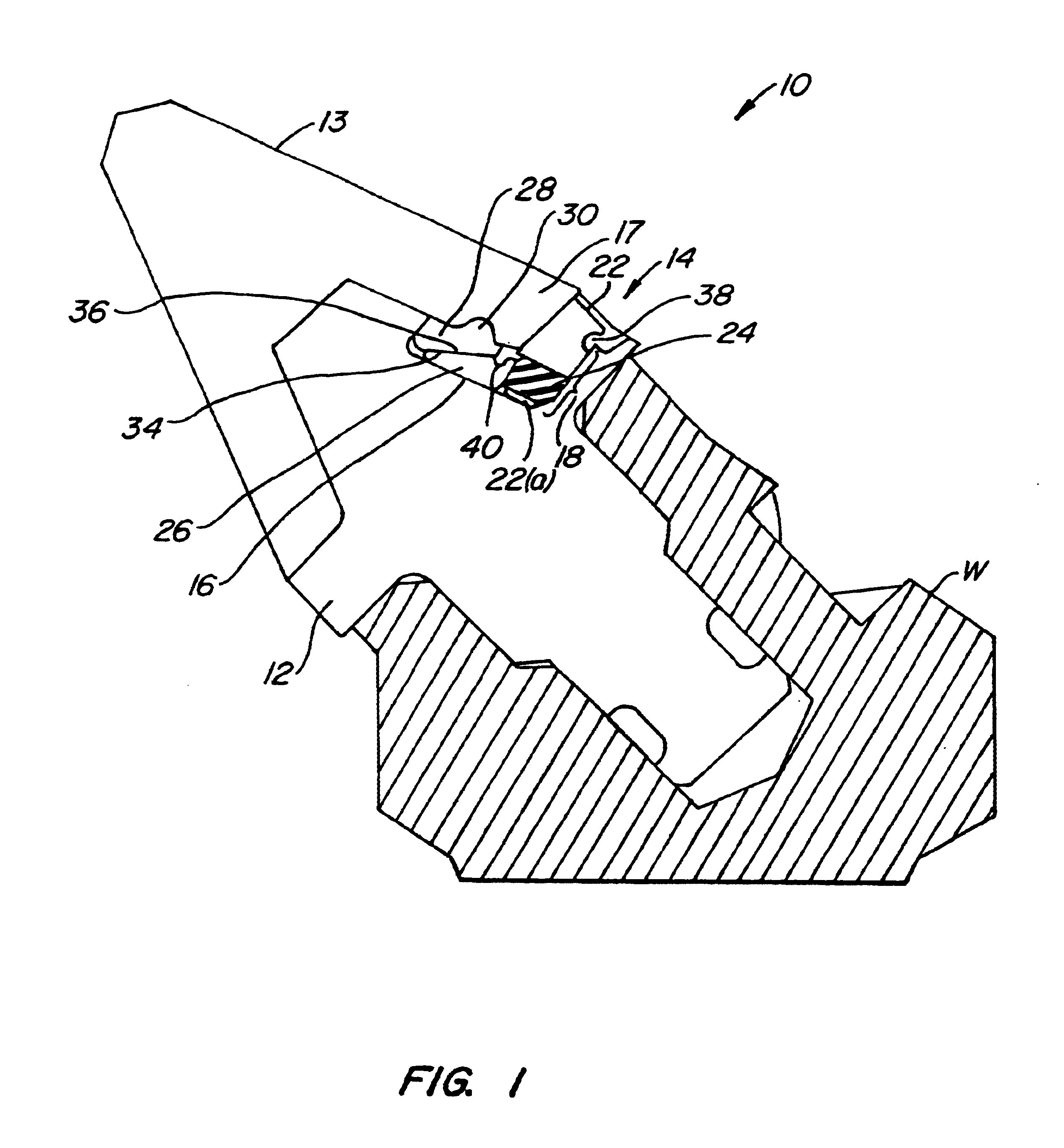
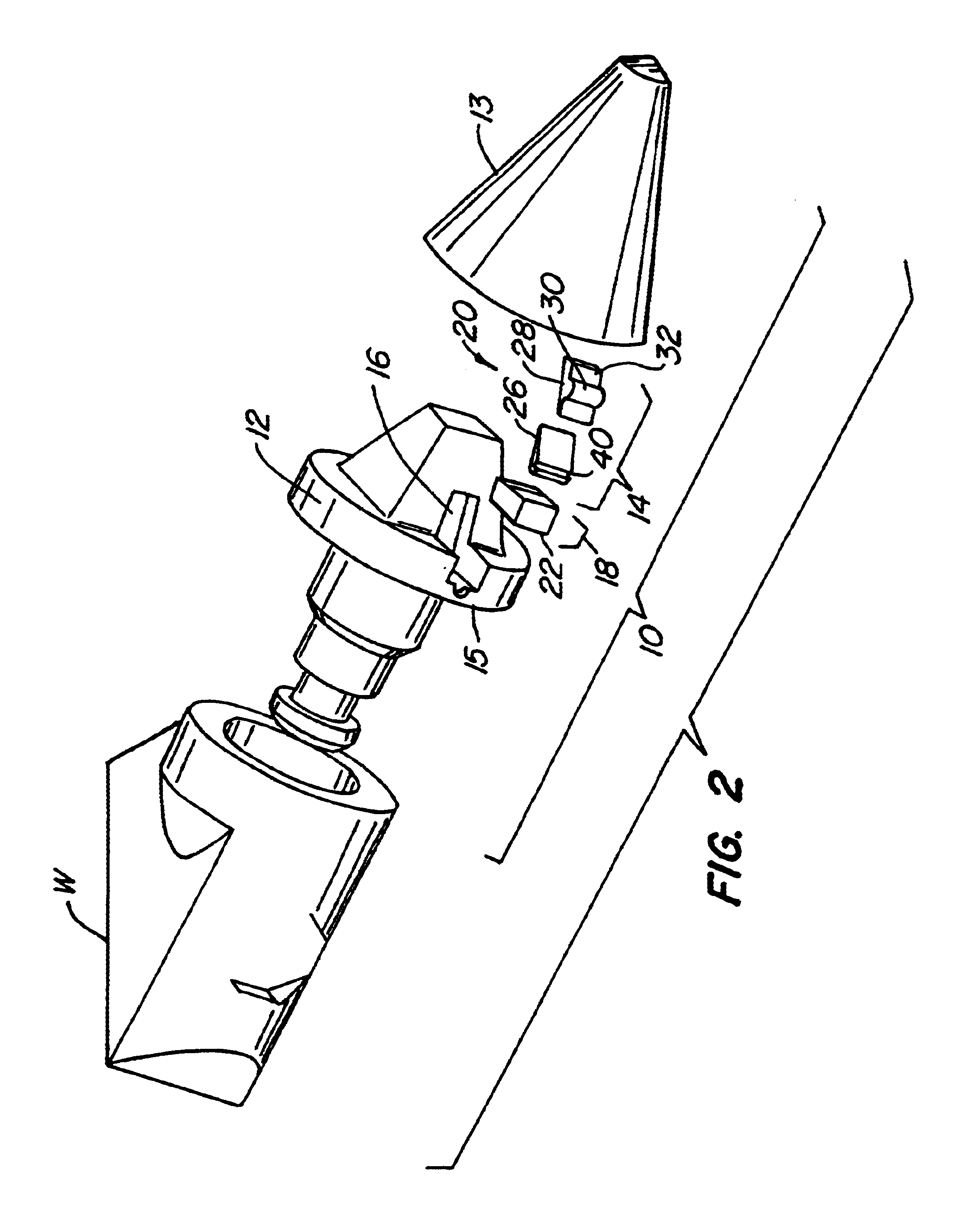
As illustrated in FIGS. 1-3, a cleat assembly 10 for a trash compactor vehicle wheel (a portion of which is labeled W) includes a cleat base 12, a replaceable cleat 13 and a connection system 14. Cleat base 12 includes a receiving portion 15 defined at least partially by a cleat base abutment wall 16. Replaceable cleat 13 includes a cleat interference portion 17.

Connection system 14 includes a biasing portion 18 and a locking portion 20. Preferably, biasing portion 18 includes an abutment section 22, with an abutment opening 22(a) extending completely therethrough, and a resilient biasing section 24. Resilient biasing section 24 is disposed in the abutment opening 22(a) and extends therefrom (as shown in FIGS. 1 and 3). Resilient biasing section 24 can include, for example, an elastomeric material (e.g., plastic or rubber), a resilient configuration (e.g., a spring) or a combination of elastomeric and non-elastomeric materials.

Locking portion 20 includes a locking section 26 and an ...


PUM


Abstract

A cleat assembly for trash compactor vehicle wheels that does not use pins to attach replaceable cleats to cleat bases on the trash compactor vehicle wheels. The cleat assembly includes a cleat base with a receiving portion that has a cleat base abutment wall. The cleat assembly also includes a re-useable connection system and a replaceable cleat with an interference portion. The connection system includes a biasing portion that is adjacent to the cleat base abutment wall and a locking portion that is adjacent to the biasing portion when the connection system is in use. The locking portion includes a locking section and an interference section that engage the interference portion of the replaceable cleat. The locking section and the interference section are capable of movement relative to one another to thereby couple the replaceable cleat to the cleat base. The biasing portion includes an abutment section with an abutment opening extending therethrough and a resilient biasing section disposed within, and extending from, the abutment opening. When the connection system is in use, the resilient biasing portion is adjacent to the cleat base abutment wall, as well as to the locking section.

Description

1. Field of the InventionThe present invention relates, in general, to trash compactor vehicle wheels and, more particularly, to cleat assemblies for trash compactor vehicle wheels.2. Description of the Related ArtTrash compactor vehicles are employed in landfill operations to move material (e.g., earth, solid waste, trash and debris) and thereby contour and compact a landfill site. The wheels of such trash compactor vehicles are typically equipped with cleats designed to grind and crush the material and to provide traction for the trash compactor vehicle as it moves the material. Since the cleats become worn with use, it is conventional for a trash compactor vehicle wheel to be equipped with a cleat assembly that includes a replaceable cleat (also referred to as a wear cap) attached to a cleat base. As a result, only the replaceable cleat normally needs (and allows) replacement, thus prolonging the usable life of the trash compactor vehicle wheel and cleat base. U.S. Pat. No. 4,919...

Claims


Application Information

Patent Timeline
Patent Type & Authority Patents(United States)
IPC IPC(8): E02D3/00E02D3/026
CPCE02D3/026
Inventor BIERWITH, ROBERT S.
Owner BIERWITH ROBERT S
Learn More