
Laser frequency stabilizer using transient spectral hole burning

a transient spectral hole and frequency stabilizer technology, applied in the direction of laser details, semiconductor lasers, electrical apparatus, etc., can solve the problems of increasing the degree of frequency mismatch, the mode spacing of the fabry-perot cavity does not nearly approach this uniformity, and the persisted spectral hole burning material, etc., to achieve accurate stabilization of laser frequency

Inactive Publication Date: 2003-11-25
MONTANA STATE UNIVERSITY
View PDF3 Cites 69 Cited by
  • Summary
  • Abstract
  • Description
  • Claims
  • Application Information

AI Technical Summary

Benefits of technology

An object of the present invention is to link together existing techniques of frequency locking and transient spectral hole burning to more accurately stabilize the frequency of a laser. Another object of the present invention is to use transient spectral hole burning materials as both laser stabilizers and signal processors.

Problems solved by technology

A difficulty is that when the frequencies are not exactly those of interest, they must be transferred through a potentially elaborate chain of precisely controlled optical and radio frequency (rf) synthesis, such as frequency doubling and mixing or parametric oscillation sums and differences.
Further, there are relatively few persistent spectral hole burning materials.
There are two principal difficulties in doing so: a) the mode spacings must match, and b) the absolute frequency of each spectral component in each comb must be aligned to overlap by tuning the laser pulse train spectrum to match those set by the Fabry-Perot reference cavity.
However, the mode spacings of the Fabry-Perot cavity do not nearly approach this uniformity.
Hence, only some central modes are exactly overlapped and those much further away accrue an increasing degree of frequency mismatch.
The composite error signal suffers to some degree from the mismatch.
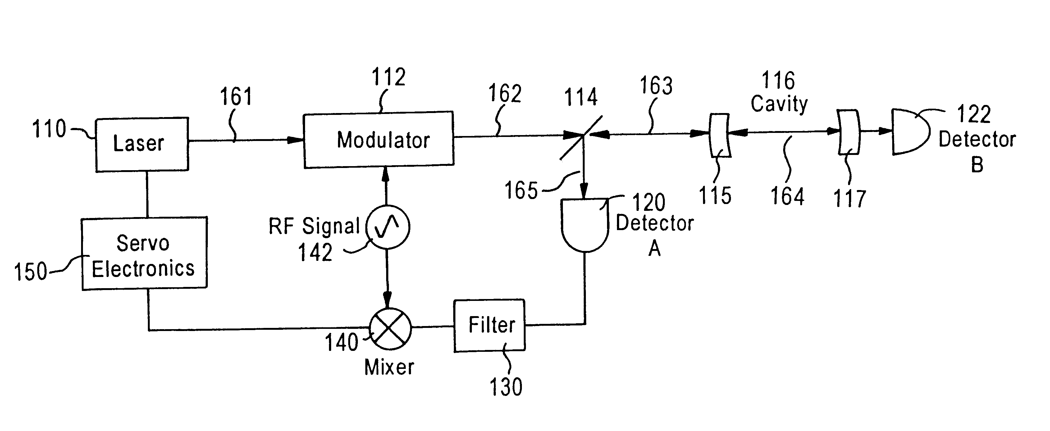
The frequency locking achievable using atomic transitions are limited by available central frequencies associated with those transitions and the characteristics of the frequency reference such as the Lamb dip.
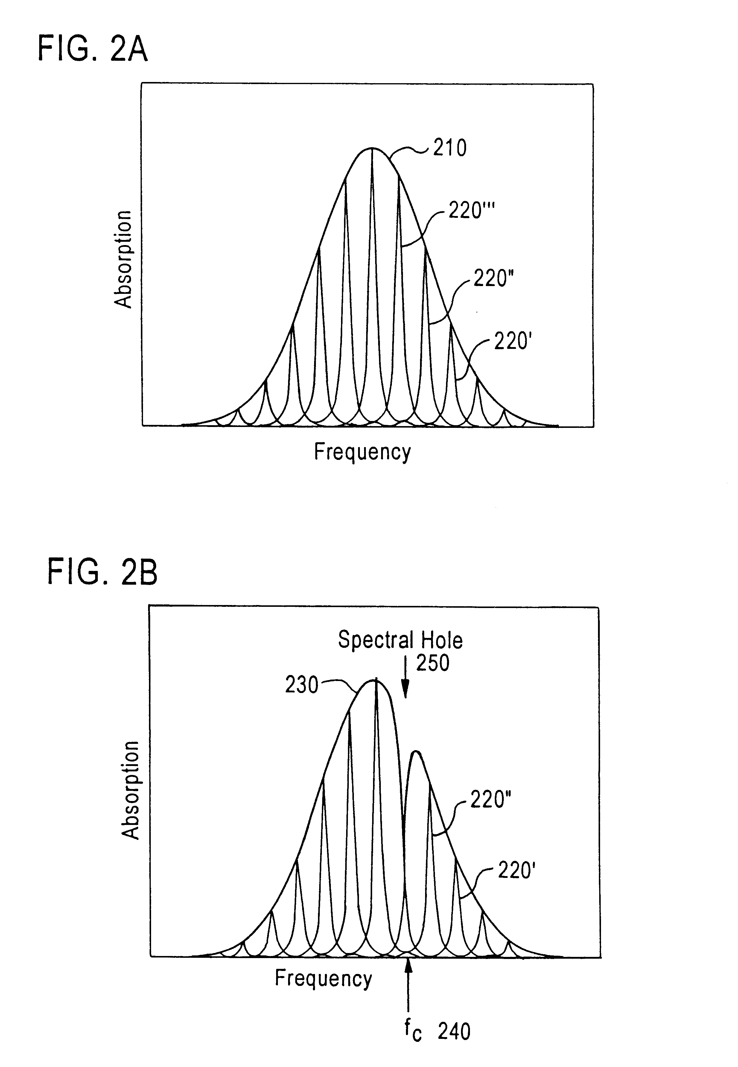
The frequency locking achievable using persistent spectral hole burning materials is limited by the broadening of the spectral hole and the range of materials that can be used as the persistent spectral hole burning material.

Method used


Image

  • Laser frequency stabilizer using transient spectral hole burning
  • Laser frequency stabilizer using transient spectral hole burning
  • Laser frequency stabilizer using transient spectral hole burning

Examples


Embodiment Construction

In the preferred embodiment, shown in FIG. 4, transient spectral hole burning material (SHBM) is used to stabilize a laser. The output of the tunable laser 410 on path 411 is split at a beam splitter 414 before entering the modulator 416 along path 415. The modulator uses an input rf signal to modulate the laser output. The output from the modulator is directed along path 417 through a transient spectral hole burning material 418. The output from the transient spectral hole burning material 418 is a reference beam which is detected by a detector 420. The detector 420 outputs a detector electrical signal. The detector signal is filtered at filter 428 to remove unwanted harmonic frequencies and to generate an error signal that is output to the mixer 426. At the mixer 426, the rf signal from the rf signal generator 424 is combined with the error signal at rf frequencies to demodulate the error signal to low frequencies where it is used as a control signal 421 that is output to the lase...


PUM


Abstract

Techniques for stabilizing a laser at a selectable frequency include splitting an output beam from an electrically adjustable laser into a first beam and a second beam. The second beam is transmitted through a modulator. Then the second beam is transmitted through a transient spectral hole burning material onto a detector. The laser is electronically adjusted in response to a detector output from the detector which senses the changes in the modulated second beam after it passes through the transient spectral hole burning material. Additions here to encompass the mode-locked case?

Description

BACKGROUND1. Field of the InventionThis application relates to a device whereby the frequency and phase of a laser is actively stabilized by locking to a transient spectral hole in a solid state or other condensed phase reference material.2. Description of the Related ArtLasers emit electromagnetic radiation characterized by the optical range of the spectrum where wavelengths are expressed in nanometers (nm) corresponding to 10.sup.-9 m, and frequencies are expressed in megaHertz (MHz) corresponding to 10.sup.6 Hz, or gigaHertz (GHz) corresponding to 10.sup.9 Hz, or teraHertz (THz) corresponding to 10.sup.12 Hz, where one Hz is one cycle per second.Previous laser stabilization techniques have relied on frequency references based on Fabry-Perot interferometer resonances or the center frequencies of transitions in atomic or molecular vapors.In the prior art, for example, the Pound-Drever-Hall laser frequency locking technique utilizes frequency modulated (FM) spectroscopy techniques t...

Claims


Application Information

Patent Timeline
IPC IPC(8): H01S5/0687H01S5/00H01S3/098H01S3/139H01S3/13H01S5/062H01S5/065
CPCH01S5/0687H01S3/1392H01S3/1394H01S3/1398H01S5/065H01S5/0657H01S5/0623
Inventor SELLIN, PETER B.STRICKLAND, NICHOLAS M.CARLSTEN, JOHN L.CONE, RUFUS L.
Owner MONTANA STATE UNIVERSITY
Learn More