Phase to sine amplitude conversion system and method

a phase to sine amplitude and conversion system technology, applied in pulse techniques, instruments, high-level techniques, etc., can solve the problems of large integrated circuit space, high power consumption, and difficulty in mobile wireless communication equipmen

Inactive Publication Date: 2003-12-02
HER MAJESTY THE QUEEN AS REPRESENTED BY THE MINIST OF NAT DEFENCE OF HER MAJESTYS CANADIAN GOVERNMENT
View PDF8 Cites 13 Cited by
  • Summary
  • Abstract
  • Description
  • Claims
  • Application Information

AI Technical Summary

Problems solved by technology

However, traditional architectures and techniques remain dependent on a look-up table and / or processing circuits that are complex, consume high power and require large integrated circuit space whether implemented as discrete components or as integrated single chip designs.
These disadvantages pose particular difficulty for mobile wireless communication equipment where portable devices, to be practical, must be physically small with low battery drain yet must retain high spectral purity.

Method used


Image

  • Phase to sine amplitude conversion system and method
  • Phase to sine amplitude conversion system and method
  • Phase to sine amplitude conversion system and method

Examples


example 1

FIG. 5 is a schematic representation of a first implementation example of a DDFS 300 including an addend generator / selector module 120A of the PSAC 110 according to the present invention. In example 1, the phase accumulator 112 accumulates a 16-bit input (the FCW from the FCU 114), on every clock cycle and passes through at most 2.sup.16 distinct states before revisiting any such state. The 12 bit output of the phase accumulator 112 is a ramp with a frequency that is equal to a clock frequency of the DDFS 300, divided by 2.sup.16, times the value of the FCW. The 12-bit output therefore takes values in the interval [0, 2.sup.12 -1], or [0, 4095], representing a fraction of a full rotation around a unit circle.

For example, an output of zero from the phase accumulator 112 corresponds to angle zero, an output of 1024 corresponds to angle 1024 / 4096.times.2.times..pi.=.pi. / 2, 2048 corresponds to angle 2048 / 4096.times.2.times..pi.=.pi., and so forth. Phase accumulator output values in the ...

example 2

FIG. 6 is a schematic representation of a second implementation example of a DDFS 400 including an addend generator / selector module 120B of the PSAC 110 according to the present invention. The signal generation component 102 and the addition / signal conditioning component 104 and their respective individual modules all function in the same way as described above. The difference between example 1 (FIG. 5) and example 2 (FIG. 6) resides in the configuration and structure of the addend generator / selector module 120B.

In particular, the four MSBs from the signal generation component 102 are applied to four multiplexers 402, 404, 406, and 408 as the control signal to identify which one of sixteen input lines each multiplexer should select. The multiplexers 402-408 each have 16 input ports, numbered 0 to 15 inclusively.

The port assignments of the multiplexer 402 are:

(a) ports 0 to 9: a signal provided by the 6 LSBs (i.e., the data signal) from the one's complement module 118 of the signal g...

example 3

FIGS. 7A and 7B represent a schematic representation of a third implementation example of a DDFS 500 including an addend generator / selector module 120C of the PSAC 110 according to the present invention to generate a digital representation of two sinusoid waveforms in quadrature. The signal generation component 102 and the addition / signal conditioning component 104 and their respective individual modules all function in the same way as described above. In example 3, the addend selector module is divided into a sine generation module 510 and a cosine generation module 520 described in more detail below.

Referring to FIG. 7B, 12 bits from the phase accumulator 112 are separated into four parts: (1) the most significant bit (MSB1), (2) the second MSB (MSB2), (3) the third MSB (MSB3), and nine least significant bits (LSB9).

The MSB1 represents the sign of the sine output data and is applied to: (a) the DAC / LPF 114A / 116A (identical to the DAC 115 and LPF 116 of FIG. 5 but shown together fo...


PUM


Abstract

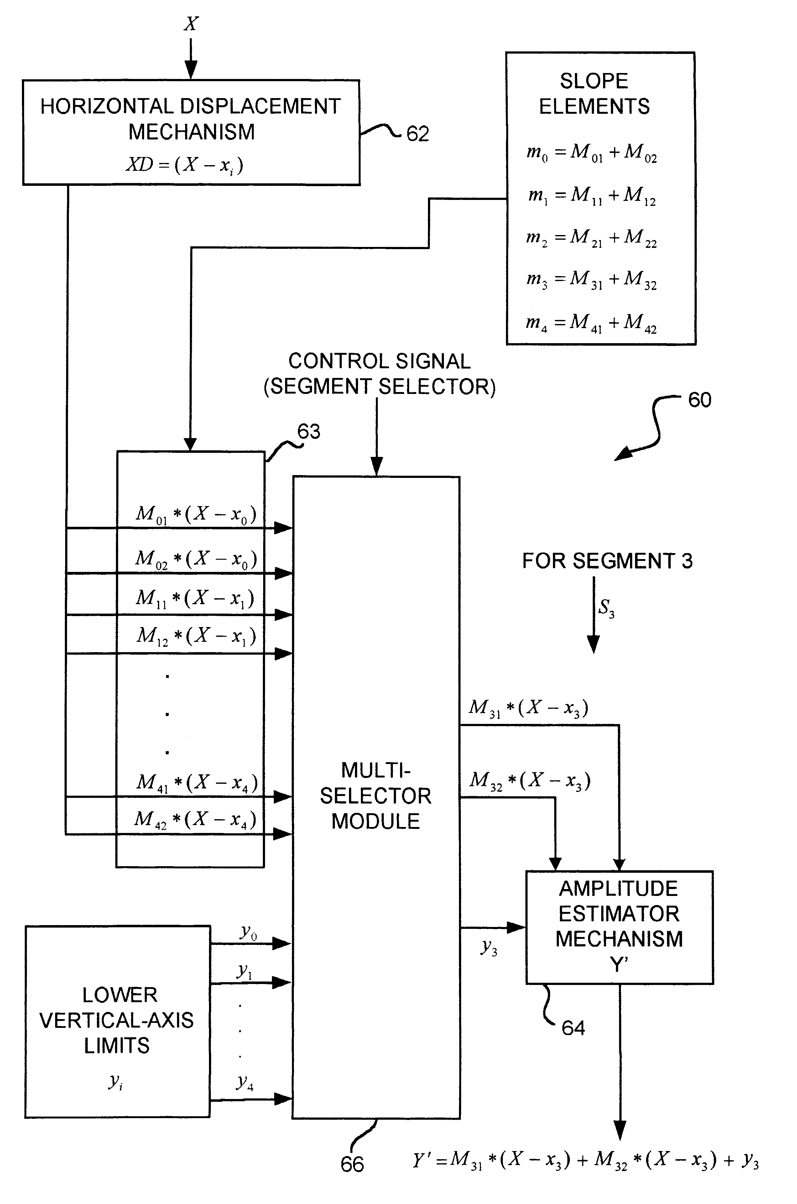
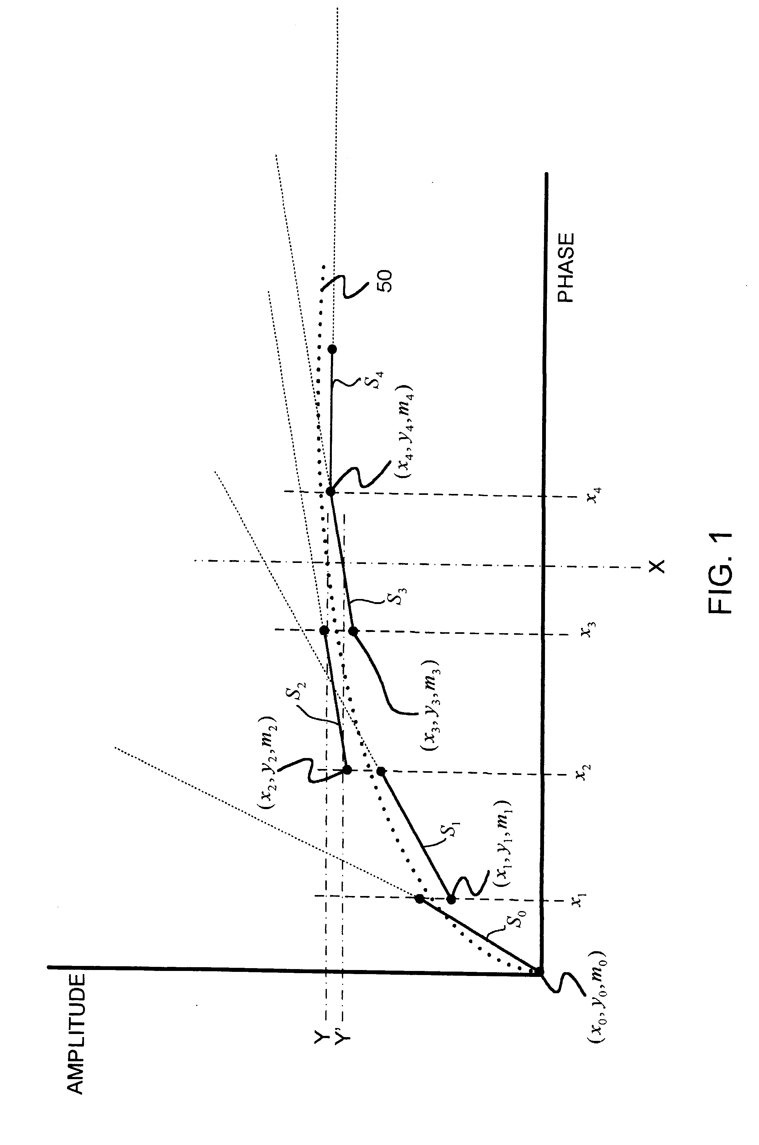
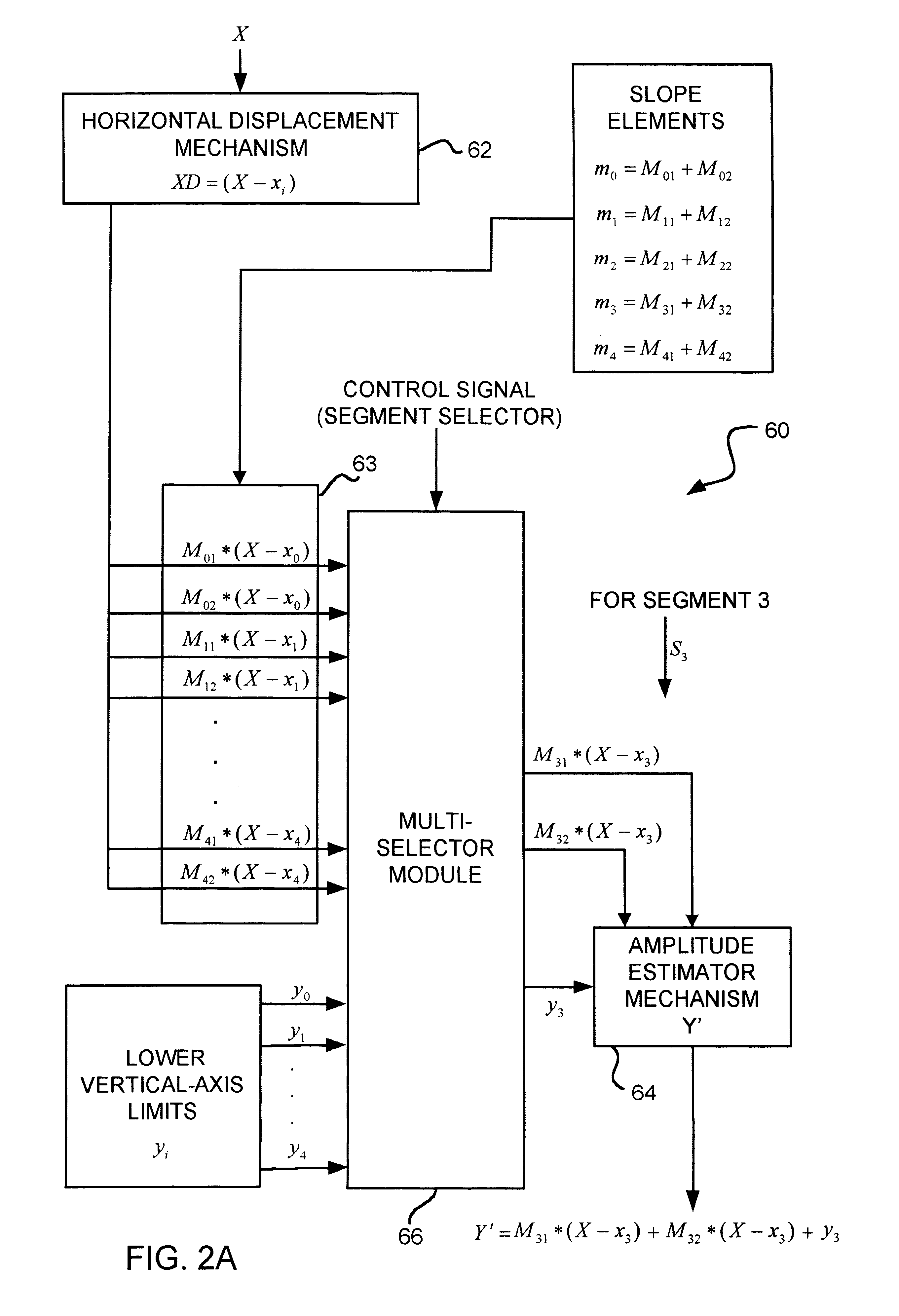
A phase-to-sinusoid-amplitude conversion system and method for use in, for example, direct digital frequency synthesizer applications. The system and method convert phase data to signal amplitude data using an approximation of the first quadrant of a sine function using a plurality of linear line segments of preferably equal length. Each segment is defined with a lower horizontal-axis bound; a lower vertical-axis bound; and a slope represented as a sum of a plurality of slope elements. Based on the approximation and for a given phase angle a set of values are evaluated, for each linear line segment, representing a product of (i) a horizontal displacement representing a difference between the prescribed phase angle and the lower horizontal-axis bound xi of a selected linear line segment where, for example, xi<X<Xi+1 and (ii) each one of the slope elements of the selected linear line segment. The approximation of the sinusoidal amplitude is then obtained by adding one of the sets of values determined above with the lower vertical-axis bound of the selected linear line segment. With appropriate selection of the number of line segments (e.g., integer power of two) and slopes elements (e.g., expressed as a sum of desired powers of two), the operations are computationally efficient and improve spectral purity and reduces implementation costs and power consumption of resulting circuitry.

Description

The present invention relates to the field of phase to sinusoid amplitude conversion (PSAC) such as used in direct digital frequency synthesizers (DDFS) for converting phase data into amplitudes of a periodic function.BACKGROUND INFORMATIONThe synthesis of a desired frequency is a fundamental requirement in many fields, and specifically in modern frequency hopping wireless communications systems. In these types of systems, it is a key requirement to change the frequency of a reference oscillator very quickly and precisely while maintaining high spectral purity. DDFS systems are recognized as being best suited for such a purpose.The basic principle of a DDFS involves the use of an accumulator to calculate phase angles around the unit circle. Sinusoid amplitudes corresponding to any such angle are obtained from a phase-to-sinusoid-amplitude converter. These samples can be passed to a digital-to-analog (DAC) converter then filtered by a low-pass filter. The output frequency is controll...

Claims


Application Information

Patent Timeline
Patent Type & Authority Patents(United States)
IPC IPC(8): H03K3/00H03M1/66G01R23/00G06F1/02G06F7/548G06G7/28H03L7/16H04B1/713
CPCG06F7/548G06F1/022Y02D30/70
Inventor LANGLOIS, JOSEPH MATHIEU PIERREAL-KHALILI, DHAMIN
Owner HER MAJESTY THE QUEEN AS REPRESENTED BY THE MINIST OF NAT DEFENCE OF HER MAJESTYS CANADIAN GOVERNMENT
Why Eureka
Try Eureka