

Locating an object using GPS with additional data
a technology of locating objects and gps, applied in wave based measurement systems, instruments, transmission systems, etc., can solve the problems of increasing the number of errors that are associated, gps data is less reliable, and it is not cost-effective for the receivers to have such atomic clocks
Inactive Publication Date: 2003-12-02
SPORTSMEDIA TECH CORP
View PDF15 Cites 74 Cited by
- Summary
- Abstract
- Description
- Claims
- Application Information
AI Technical Summary
Problems solved by technology
However, it is not cost effective for the receivers to also have such atomic clocks.
There are a number of errors that are associated with GPS ranging, including errors due to the Earth's ionosphere and atmosphere.
Additionally, basic geometry itself can magnify these errors.
So, if two receivers are fairly close to each other, say within a few hundred kilometers, the signals that reach both of them will have traveled through virtually the same slice of atmosphere, and will have virtually the same errors.
Thus, if fewer than four satellites are available, a GPS receiver typically can not determine its location.
However, there may be some applications where gaps in validly determined GPS derived locations can not be tolerated.
For example, an air traffic control system can not afford to lose a fix on an airplane near an airport.
As discussed above, using an atomic clock in a GPS receiver can be very expensive and make the cost of the GPS receiver prohibitive.
However, because the quartz oscillator will drift overtime, data from the quartz oscillator can only be used for 5-10 seconds.
While using a quartz oscillator (or other high precision clock) can allow the system to continue to function for a very brief period of time while one of four satellites are not in view of the GPS receiver, the system is still not reliable enough for many applications.
For example, if fewer than three satellites are available than the information from the quartz oscillator does not provide sufficient data to make up for the loss of satellite data.
Additionally, if the length of time that the fourth satellite is not available to the GPS receiver is greater than the 5-10 second range of the quartz oscillator, then the quartz oscillator no longer provides additional information necessary to determine a three dimensional location.
Method used
View moreImage
Smart ImageViewing Examples

Examples
Embodiment Construction
has been presented for purposes of illustration and description. It is not intended to be exhaustive or to limit the invention to the precise form disclosed, and obviously many modifications and variations are possible in light of the above teaching. The described embodiments were chosen in order to best explain the principles of the invention and its practical application to thereby enable others skilled in the art to best utilize the invention in various embodiments and with various modifications as are suited to the particular use contemplated. It is intended that the scope of the invention be defined by the claims appended hereto.
Login to View More PUM
 Abstract
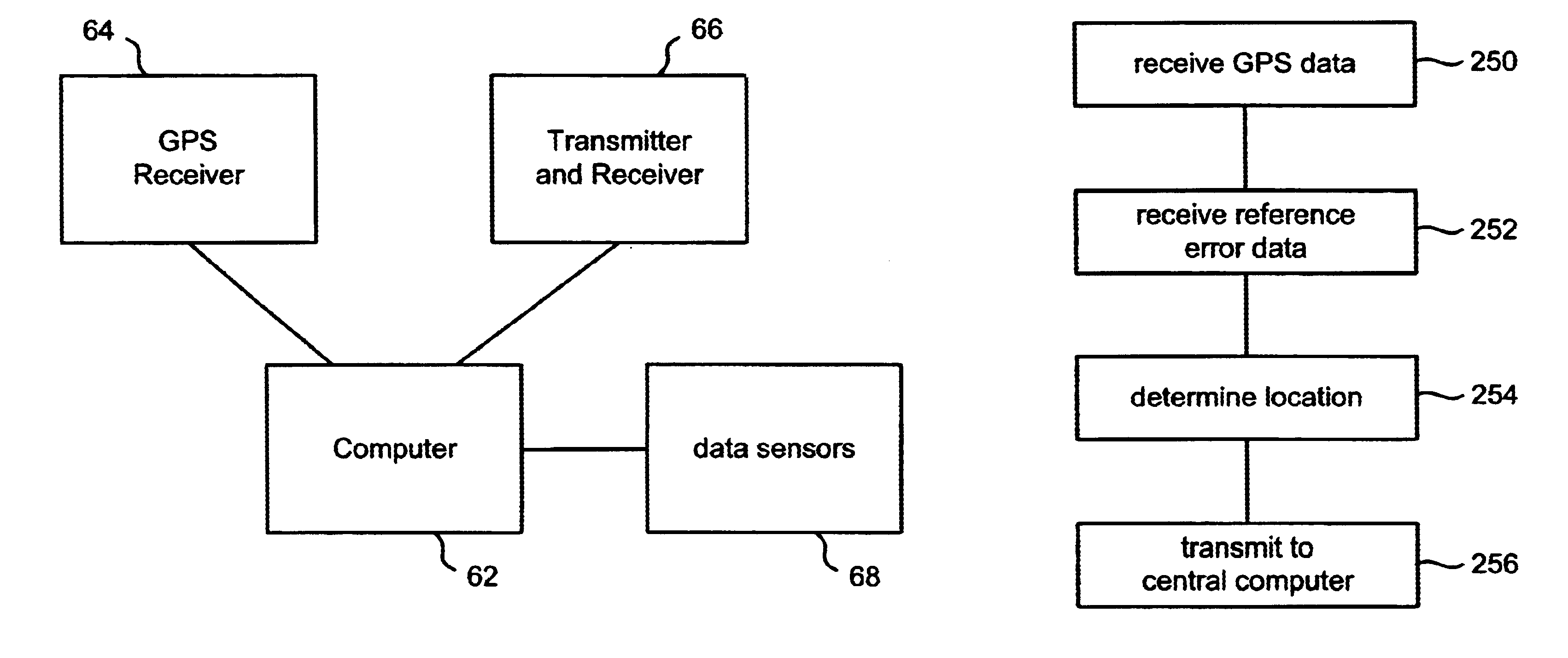
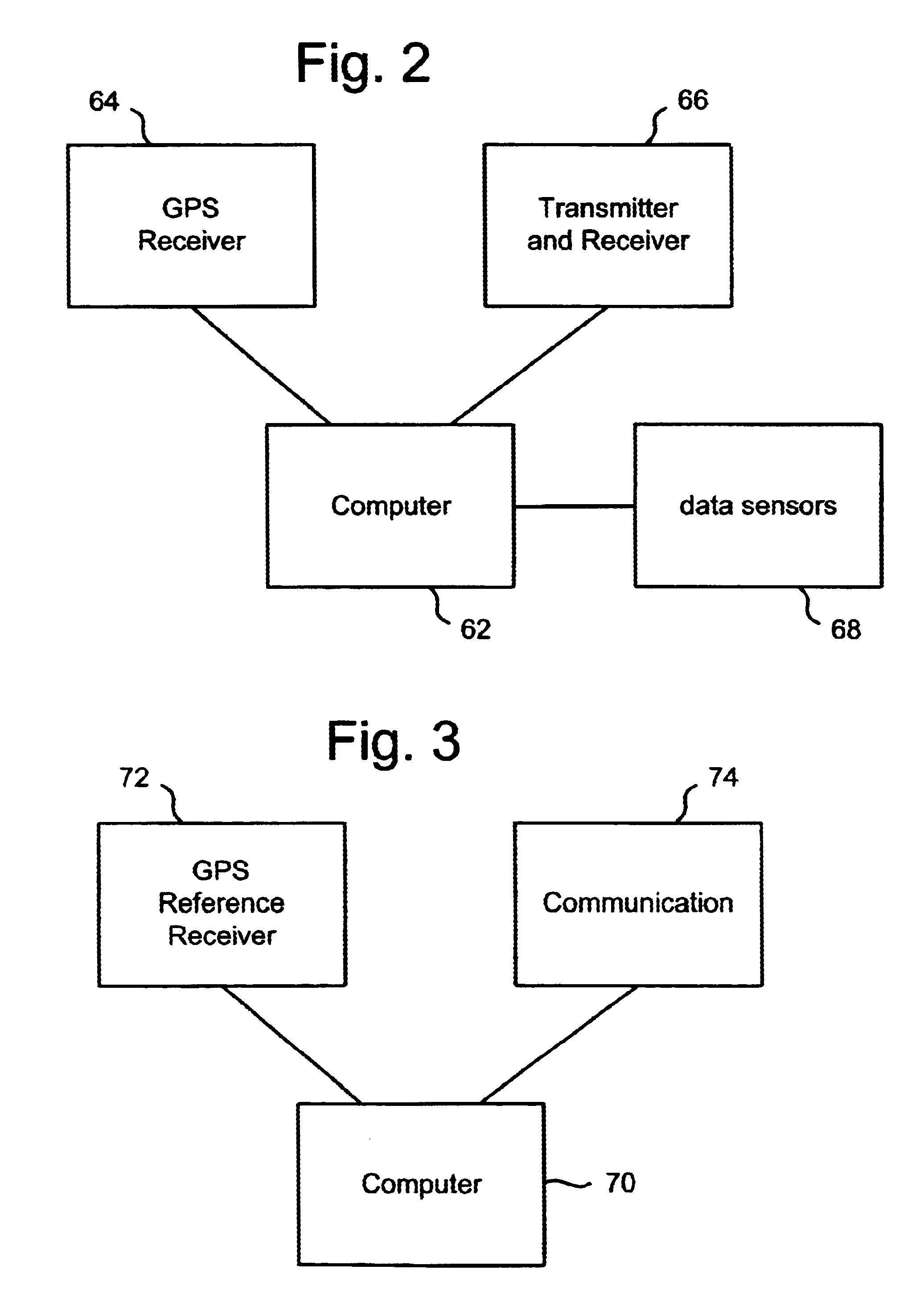
A system is disclosed that uses GPS and additional data to determine the location of an object. Typically, GPS receivers need valid data from four satellites to accurately determine a three dimensional location. If a GPS receiver is receiving valid data from fewer than four satellites, then additional data is used to compensate for the shortage of satellites in view of the GPS receiver. Examples of additional data includes a representation of the surface that the object is traveling on, an accurate clock, an odometer, dead reckoning information, pseudolite information, and error correction information from a differential reference receiver. An exemplar use of the disclosed system is to concurrently track a set of one or more automobiles during a race. The determined locations of the automobile can be used to provide route information, to generate statistics and / or to edit video of one or more of the automobiles.
Description
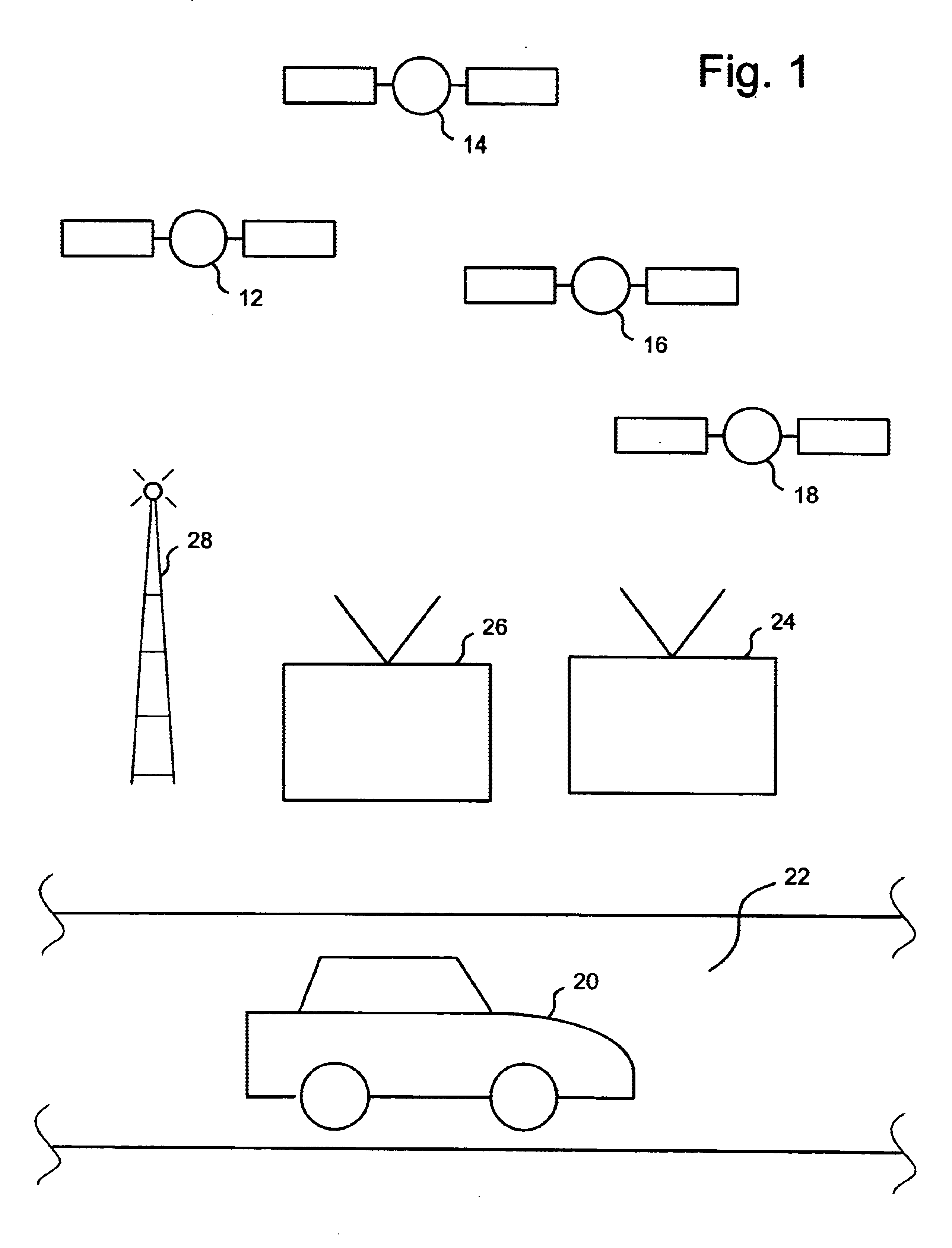
1. Field of the InventionThe present invention is directed to a system for determining the position of an object.2. Description of the Related ArtTechnologies for tracking moving objects are in demand. For example, systems are used to track airplanes, automobiles, persons, objects at sporting events and other objects of interest. Examples of tracking objects at sporting events include systems for tracking hockey pucks during a hockey game using infrared technology, tracking objects using RF signals and tracking objects using pattern recognition technology.One technology that has become popular for tracking objects is the use of the Global Positioning System (GPS). GPS is a satellite based navigation system operated and maintained by the U.S. Department of Defense. GPS consists of a constellation of 24 GPS satellites providing worldwide, 24 hour, three dimensional navigational services. By computing the distance to GPS satellites orbiting the earth, a GPS receiver can calculate an ac...
Claims
Login to View More Application Information
Patent Timeline
 Patent Type & AuthorityPatents(United States)
IPC IPC(8): G01C21/28G01S1/00G01S5/14G01S5/00G01S19/11G01S19/19G01S19/22G01S19/41G01S19/42G01S19/45G01S19/46G01S19/47G01S19/50
CPCG01C21/28G01S5/0027G01S5/0036G01S5/0054G01S19/11G01S19/50G01S19/41G01S19/426G01S19/45G01S19/46G01S19/47G01S19/19
InventorCAVALLARO, RICHARD H.HONEY, STANLEY K.MILNES, KENNETH A.WHITE, MARVIN S.
OwnerSPORTSMEDIA TECH CORP