Collector and separator apparatus for lawn and garden

a technology of separator and lawn and garden, which is applied in the direction of gas current separation, turf growing, grain treatment, etc., can solve the problems of difficult to remove thick layers of debris, difficult to collect leaves and other debris, and no longer so effective in collecting leaves and other debris close to the ground, etc., and achieve the effect of effectively removing deep piles of leaves and other debris

Inactive Publication Date: 2003-12-09
BESTRAKE
View PDF52 Cites 34 Cited by
  • Summary
  • Abstract
  • Description
  • Claims
  • Application Information

AI Technical Summary

Benefits of technology

It is an object of the present invention to provide a machine which effectively removes deep piles of leaves and other debris. In preferred embodiments, the thin layer of residual debris which might otherwise be left for later removal in another step is cleanly removed at the same time.
Further in FIG. 9, upon being filled with retained debris 124, hopper 114 may be opened by sliding apart upper and lower flanges 126, allowing retained debris 124 accumulated therein to be discarded. Thus, another feature of the invention is in providing a debris-collection receptacle which can be emptied quickly and easily.

Problems solved by technology

Homeowners, commercial-property owners, and companies who provide care for lawns have an ongoing challenge of how to remove leaves, grass clippings, and other debris from lawns, gardens and paved surfaces, particularly when the debris accumulates to a depth of over an inch.
However, the dilemma with many prior-art units is that while they are reasonably adapted to vacuum a thin layer of debris from the ground, they do not function well when there is a thick layer of leaves or other debris.
If the collector duct is raised to be able to take leaves from the top of the overlayer, it is no longer so effective in collecting the leaves and other debris close to the ground.
Accordingly, while the available machines are somewhat effective in removing the thin layers of debris, the task of collecting thick layers of debris, particularly deep piles of leaves, remains quite problematic.
Such devices are poorly adapted to the tasks for which machine assistance is needed most.
However, as leaf fragments and other debris collect on the filter, resistance to the flow of air increases, diminishing the air flow rate, and thereby, reducing the effectiveness of the vacuum pick-up opening.

Method used


Image

  • Collector and separator apparatus for lawn and garden
  • Collector and separator apparatus for lawn and garden
  • Collector and separator apparatus for lawn and garden

Examples


example 2

Following the experience of example 1, collecting leaves with a conventional 26-inch, two-stage snow blower was attempted to see if the auger-feed mechanism would function with leaves. Indeed, the auger readily fed even the deepest piles of leaves into the second-stage blower, which blew them 10-15 feet away. However, this approach left a thin layer of leaves and other debris on the lawn where the pick-up auger had passed.

The conclusion was that a machine with a similar auger-feed pick-up would collect even deep piles of leaves. However, the user would need to go over the lawn a second time with a different machine to collect the thin layer of residual leaves and other debris.

example 3

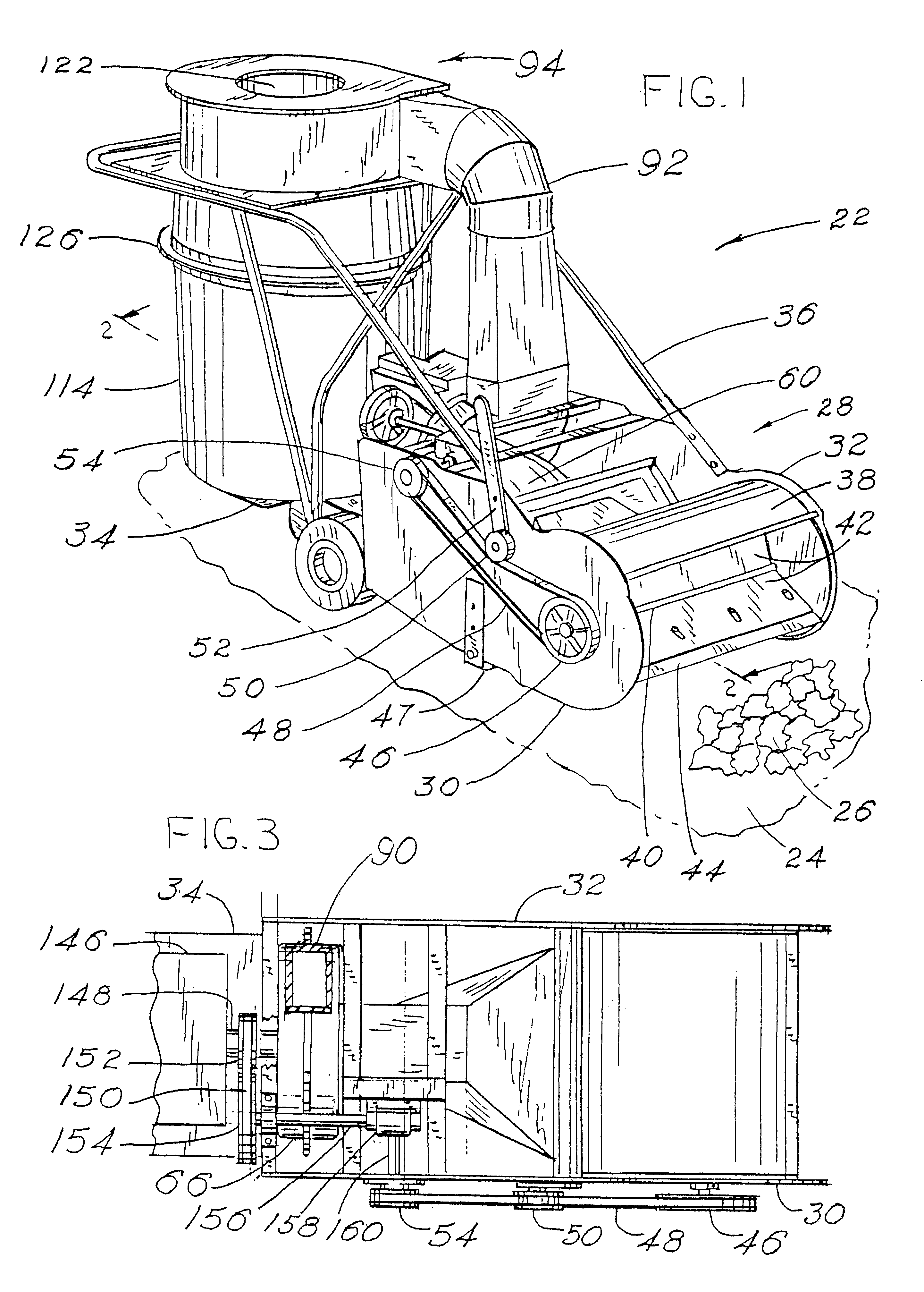
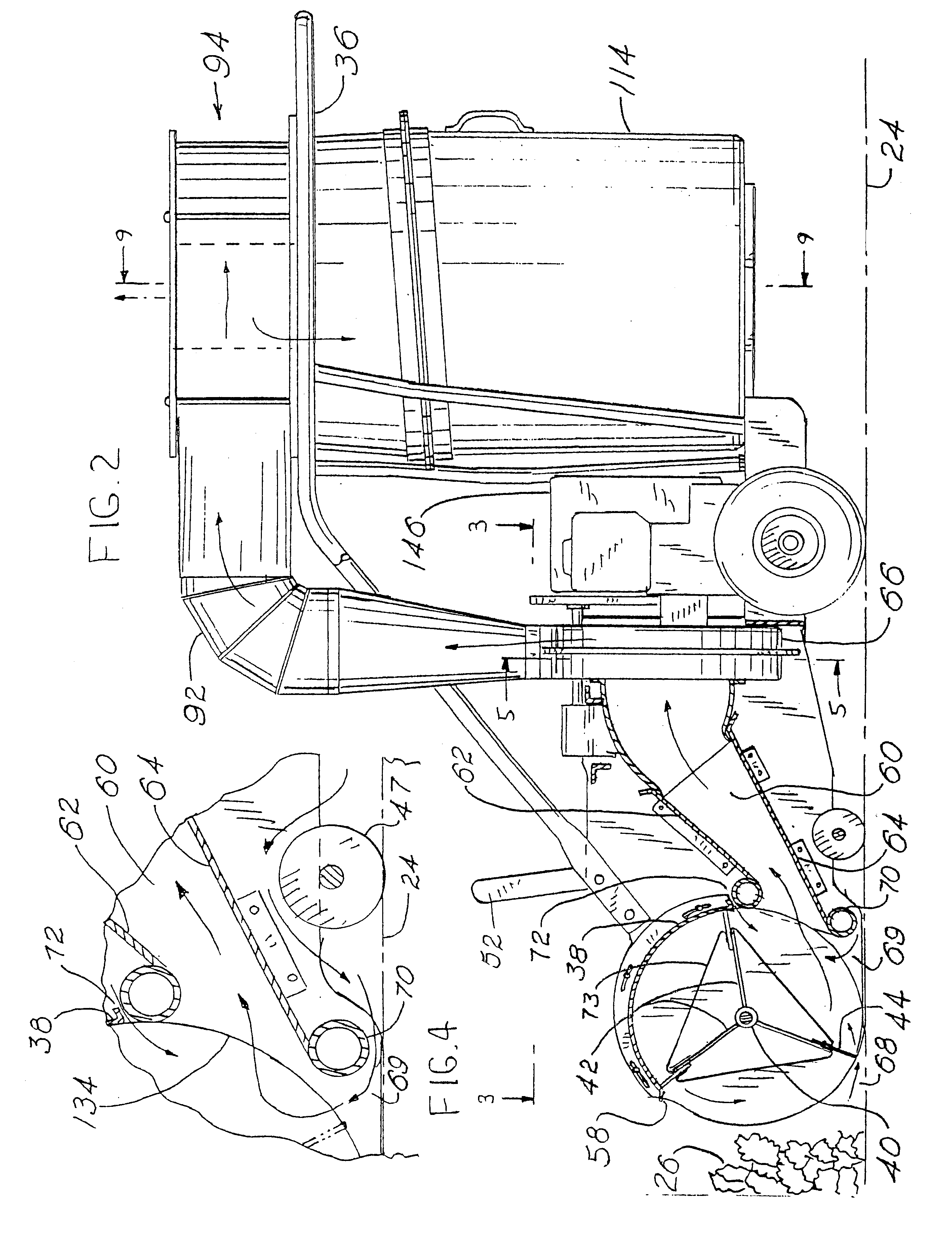
A machine of the current invention was built according to the drawings in FIGS. 1-11. A Yard Man 5-horsepower chipper-shredder-vacuum machine built by MTD Products was purchased; the chipper-shredder unit and attached drive motor were removed from the purchased machine; and then they were mounted on the base plate of the current machine. The machine width between the left support plate and the right support plate was 24." The collector rotor diameter was 15", and it turned 65 revolutions per minute. The front, upper edge of the housing over the rotor was about 131 / 2" above the support surface. The lowermost portion of the lower collector lip was about 1" above the supporting surface when measured with the machine sitting on a concrete slab. The collector duct had an entrance opening 21 / 2" high and 24" wide with a cross sectional area of 60 square inches, an exit opening about 6" high and 9" wide with a cross sectional area of about 54 square inches, and a convergence angle of 76.deg...

example 4

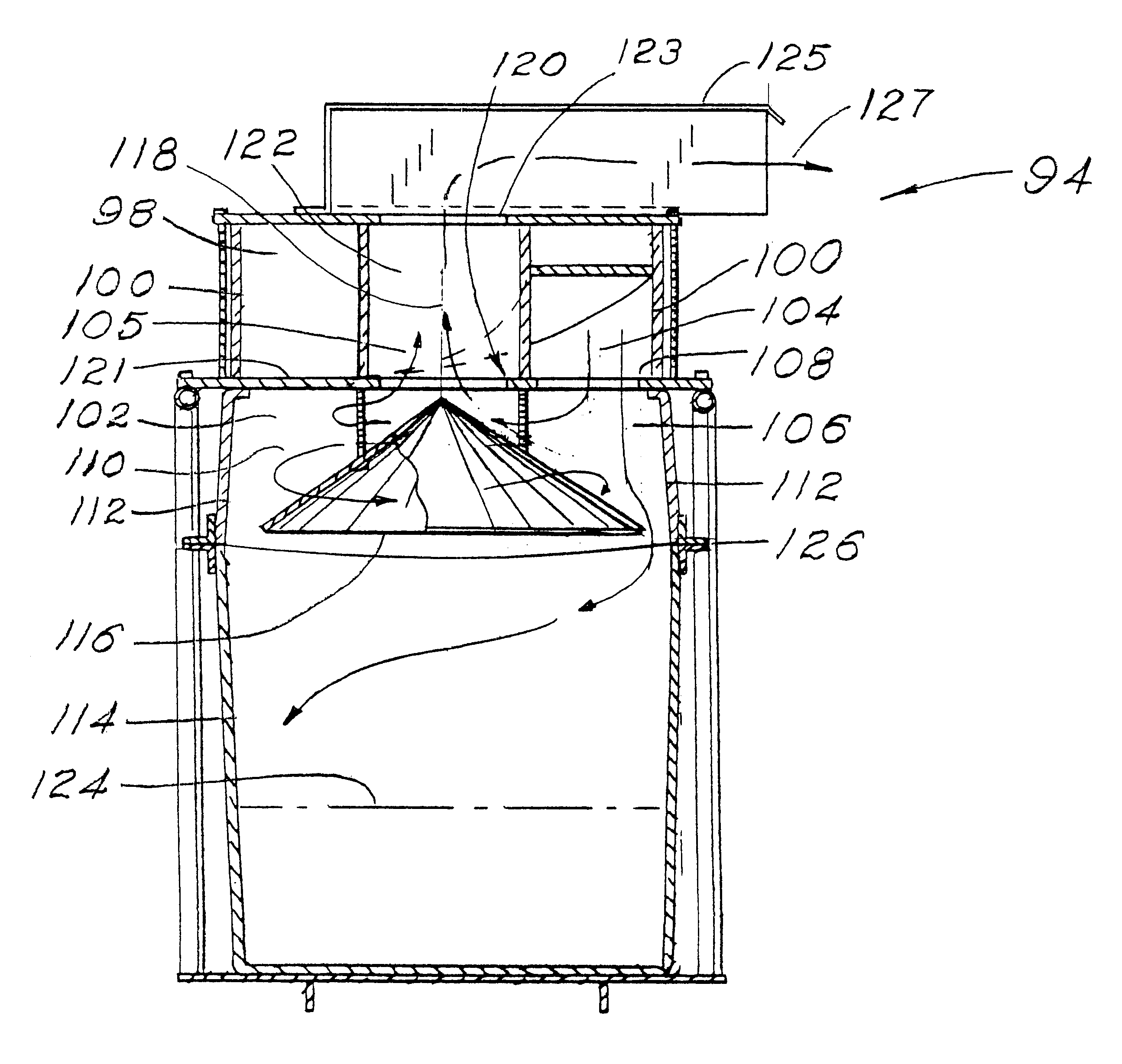
The machine of Example 3 was modified as follows: In order to increase the air flow rate, (1) the engine speed was increased from 3450 to 3680 revolutions per minute; (2) the constriction in the primary separation loop was removed, leaving the channel size throughout the loop at 4" wide and 8" high; (3) the transfer opening was enlarged to about 100 square inches; and (4) the separator exhaust port was enlarged from 7" to 91 / 8" diameter. The airflow rate was then measured at 1000 cubic feet per minute (41.7 cfm per inch of machine width). The collector rotor speed was increased from 65 to 276 revolutions per minute. In order to reduce the number of leaves carried over the top of the turning collector rotor, the stripping slot was opened to 1". The diameter of the baffle in the separator was reduced, leaving an annular radial clearance of about 23 / 8" between the baffle perimeter and the outside wall of the secondary chamber. The perimeter of the baffle was 51 / 4" below the ceiling of ...


PUM


Abstract

An apparatus for collection and reduction of yard debris combining a frontally facing rotor-assisted vacuum pick up with a chipper-shredder-blower unit to induce airflow for entraining debris collected at the vacuum pick up; reduce the entrained debris to a more manageable volume; and impel the reduced debris to a free-flow-separator device for removing the debris from the air in which it is entrained.

Description

This invention relates to an apparatus for collection and reduction of yard debris in thick layers and deep piles.Homeowners, commercial-property owners, and companies who provide care for lawns have an ongoing challenge of how to remove leaves, grass clippings, and other debris from lawns, gardens and paved surfaces, particularly when the debris accumulates to a depth of over an inch. Several companies now manufacture and sell combination vacuum-chipper-shredder machines intended for this purpose. Some U.S. patents illustrating the range of these machines are as follows: U.S. Pat. Nos. 5,931,396 and 5,799,365, both assigned to MTD Products; U.S. Pat. Nos. 5,381,970 and 5,231,827, both assigned to Garden Way Incorporated; and U.S. Pat. No. 5,642,864, assigned to Simplicity Manufacturing, Inc. However, the dilemma with many prior-art units is that while they are reasonably adapted to vacuum a thin layer of debris from the ground, they do not function well when there is a thick layer ...

Claims


Application Information

Patent Timeline
Patent Type & Authority Patents(United States)
IPC IPC(8): A01G1/12B02C18/06B02C13/00B02C13/04B02C18/14B02C13/282A01D43/00
CPCA01G1/125A47L9/1608A47L9/165A47L9/1658B02C13/282B02C18/06B02C18/14B02C13/04B02C2201/066A01G20/47
Inventor DUNNING, CHARLES E.SAATHOFF, RICHARD B.
Owner BESTRAKE
Why Eureka
Try Eureka