Optical transmitting apparatus and optical repeating apparatus

a technology of optical repeating and optical transmitting equipment, which is applied in the direction of electromagnetic repeaters, multiplex communication, instruments, etc., can solve the problems of high investment cost of optical cables, high labor costs of administrators who execute control, and loss of transmission in optical cables, etc., and achieve the effect of efficient system operation

Inactive Publication Date: 2003-12-09
FUJITSU LTD
View PDF10 Cites 17 Cited by
  • Summary
  • Abstract
  • Description
  • Claims
  • Application Information

AI Technical Summary

Benefits of technology

Accordingly, transmission light and reception light can be transmitted through optical fiber cables in one system, so that the installation cost and maintenance cost of an optical cable cost can be decreased. Since cut of the optical cable is performed by a monitoring function using pumping light and residual pumping light in a two-way transmission, reliability and safety of the system can be remarkably improved.
Accordingly, optical output level adjustment in the repeating station is most suitably set according to an actual transmission distance, which allows an efficient system operation.

Problems solved by technology

In the long distance transmission, a transmission loss generates in an optical cable.
However, the techniques disclosed in Japanese Patent Laid-Open Publication No. 9-113941 and Japanese Patent Laid-Open Publication No. 9-200144 have three types of problems.
First, since a plurality of pumping sources are transmitted through optical cables differing from an optical cable through which optical signals are transmitted, the investment cost of the optical cables is high.
The second problem is that a precise control is necessary in each terminal station, which requires a labor cost of an administrator who executes the control.
The third problem is that the method for detecting cut of an optical cable is not established.

Method used


Image

  • Optical transmitting apparatus and optical repeating apparatus
  • Optical transmitting apparatus and optical repeating apparatus
  • Optical transmitting apparatus and optical repeating apparatus

Examples


first embodiment

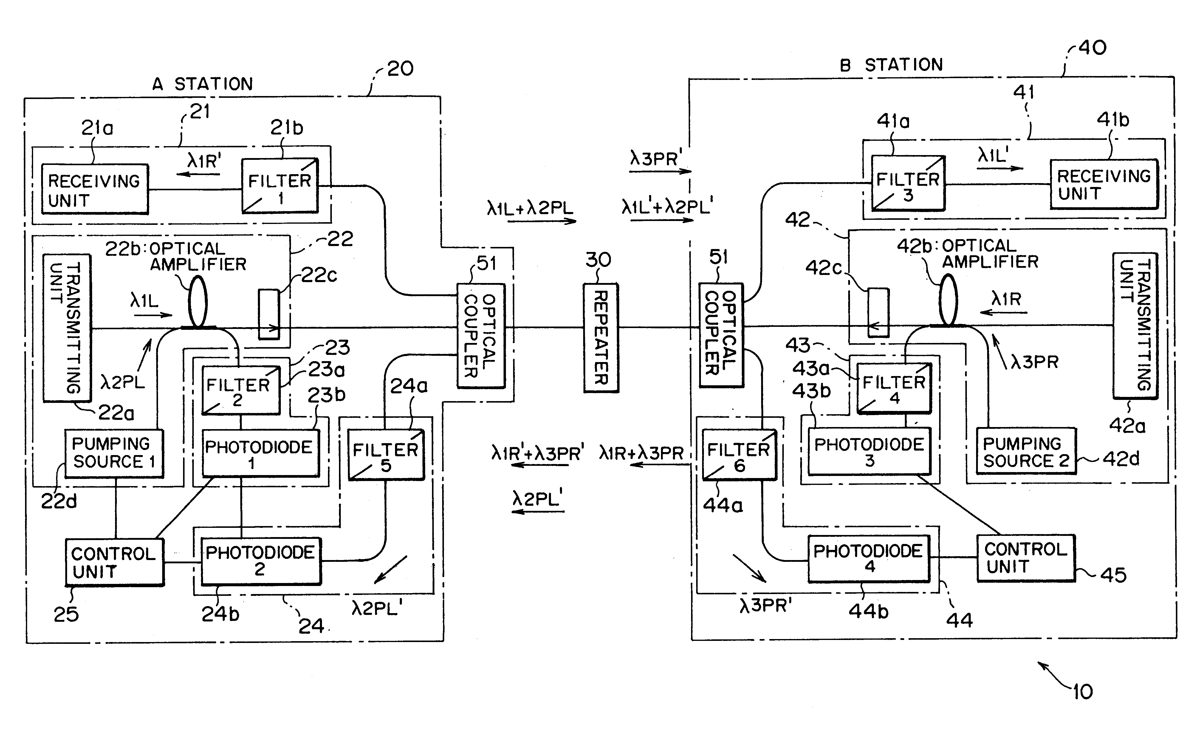
FIG. 1 is a diagram showing a structure of an optically amplified two-way transmission remote pumping system according to this invention. An optically amplified two-way transmission remote pumping system 10 shown in FIG. 1 is a system which can transmit / receive transmission light, reception light and pumping light through optical fiber cables of one system.

The optical system 10 shown in FIG. 1 comprises a transmitting station (A station) 20, a repeating station 30, and a receiving station (B station) 40, where the stations are connected by optical cables to be able to transmit optical signals in two ways. In the repeating station 30, the output level of a pumping source thereof is controlled. Between the stations, a control on the optical level and detection of cut of the optical cable are carried out, whereby the system can be automatically restored. In the following descriptions, the optically amplified two-way transmission remote pumping system will be occasionally referred as an...

fourth embodiment

With the above structure, repeater transmission is performed. In FIG. 12, an operation of a controlling means 25 in the transmitting station 20e is as follows. An optical output level of .lambda.2PL is monitored by a first optical detector 23b. A level of returned light .lambda.2PL' from the first repeating station 30e is monitored by a second optical detector 24b. In the method described in the fourth embodiment, an actual transmission loss between the transmitting station 20e and the first repeating station 30e is calculated, and displayed on a display unit 53a. The controlling means 25 performs a gain control on the first pumping source 22d so that the optimum optical level is inputted to the first repeating station 30e.

An operation of the controlling means 45 in the receiving station 40e is as follows. An optical output level of .lambda.3PR is monitored by a third optical detector (photodiode 3) 43b. Returned light .lambda.3PR' from the second repeating station 30e' is monitored...

second embodiment

(B) Description of Second Embodiment of the Invention

FIG. 27 is a diagram showing a structure of an optical system according to a second embodiment of this invention. An optical system 10i shown in FIG. 27 is a similar optical system to those described above. Structures of a transmitting station 20f " and a receiving station 40f " are equivalent to the transmitting station 20f and the receiving station 40f shown in FIG. 16 to which disconnect detecting means 26 and 46 are added, and a reflecting means (reflecting element 1) 11a and a reflecting means (reflecting element 2) 11b are disposed on outputs' side of isolators 22c and 42c, respectively. Each of these reflecting means 11a and 11b reflects an optical signal at a specific wavelength contained in a received optical signal, a specific wavelength reflecting element such as a fiber grating or the like being used therefor. In FIG. 27, parts designated by like reference characters have like or corresponding functions described above...


PUM


Abstract

In an optical amplifying technique using remote pumping, an optical transmitting apparatus and an optical repeating apparatus are provided. An optical repeating apparatus comprises a first optical transmitting unit, a first loopback unit, a second optical transmitting unit, a second loopback unit, and four optical couplers, wherein transmission light and reception light are transmitted through one optical fiber cable, whereby the installation cost and maintenance cost of the optical cable are decreased. Disconnect of the optical cable is detected by a monitoring function using pumping light and residual pumping light, whereby reliability and safety of the system are remarkably improved. Additionally, adjustment of the optical output level of the repeating station can be most suitably set according to an actual transmission distance.

Description

The present invention relates to an optically amplified transmission apparatus and a repeater of a remote pumping type in an optical two-way transmission system, for example. Particularly, the present invention relates to an optical transmitting apparatus and an optical repeating apparatus suitable for use in a system which can transmit transmission-reception light and pumping light through optical fiber cables in one system, remotely control the output level of a pumping source, fulfil an optical level controlling function, a disconnect detecting function and an automatic restoring function for an optical cable among the stations.Long distant transmission using optical fiber cables (hereinafter referred as optical cables, occasionally) is performed in order to transmit a large volume of data at a high speed, in recent years. In the long distance transmission, a transmission loss generates in an optical cable. For this, the optically amplified transmission system transmits transmiss...

Claims


Application Information

Patent Timeline
Patent Type & Authority Patents(United States)
IPC IPC(8): H04B10/17H04B10/08H04B10/25H01S3/00H04B10/00H04B10/035H04B10/07H04B10/077H04B10/079H04B10/29H04B10/294H04B10/297H04J14/00H04J14/02
CPCH04B10/07H04B10/2972H04B10/291H04B10/075
Inventor SHIRAI, KATSUHIRO
Owner FUJITSU LTD
Why Eureka
Try Eureka