

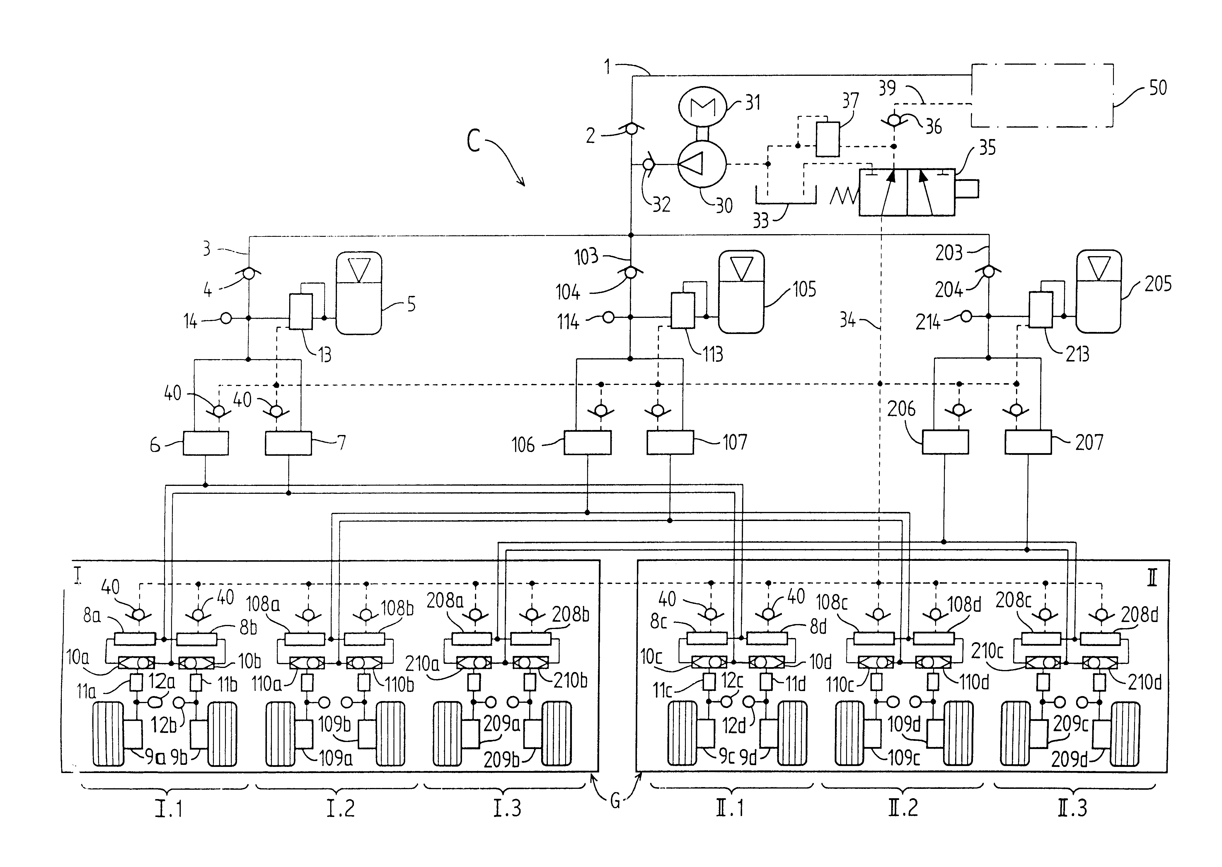
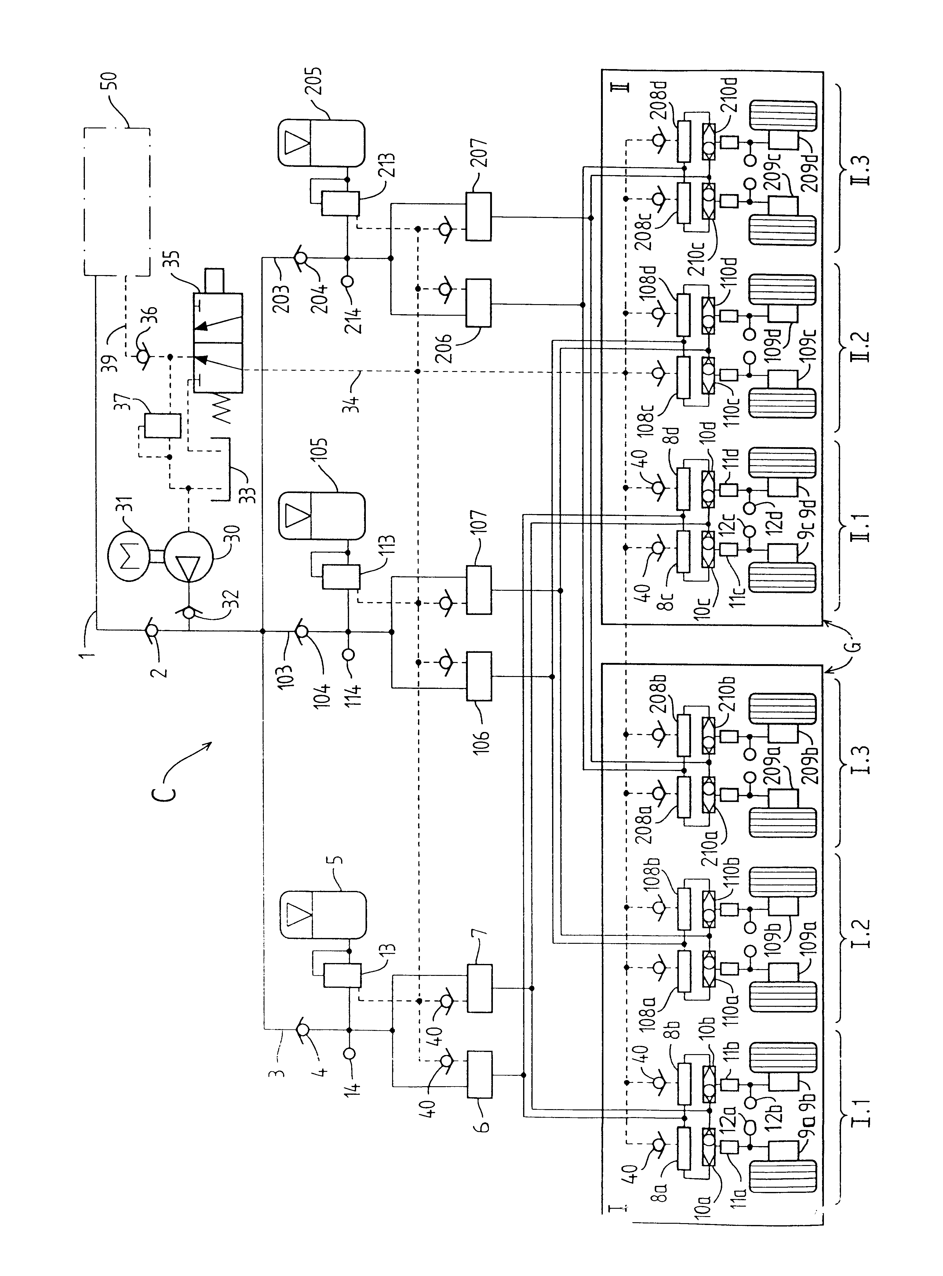
Architecture for the hydraulic braking system of an aircraft
a hydraulic braking system and aircraft technology, applied in the direction of braking systems, aircraft braking arrangements, servomotors, etc., can solve the problems of not being able to maintain braking ability, affecting only a single landing gear group, and failure of any one circui
- Summary
- Abstract
- Description
- Claims
- Application Information
AI Technical Summary
Benefits of technology
Problems solved by technology
Method used
Image

Examples
Embodiment Construction
A braking architecture of the invention comprises one hydraulic circuit per group of landing gear units fitted with brakes, and thus in principle it is applicable to main landing gear units, even though it is not impossible for some or all of the auxiliary landing gear units optionally to be fitted with brakes and therefore to be incorporated in one of the landing gear groups or to constitute an independent group.
For reasons of safety, the landing gear groups under consideration are assumed to be disposed symmetrically about the plane of symmetry of the aircraft, so that in the event of one of the circuits malfunctioning, there need be no question of managing residual braking capacity that is asymmetrical, which would be very difficult in terms of controlling the aircraft properly. Thus, for the intended jumbo-sized aircraft, the fuselage landing gear group and the wing landing gear group are, in practice, arranged symmetrically about the plane of symmetry of the aircraft.
In the inv...
PUM
 Abstract
Description
Claims
Application Information