Method and system for improved analog signal detection

a technology of analog signal detection and detection system, applied in the field of methods and systems for improving analog signal detection, can solve the problems of affecting the detection of such signals in environments where noise or speech is present, and affecting the detection of valid dtmf signaling tones, etc., to achieve the effect of increasing the accuracy of determining

Inactive Publication Date: 2003-12-16
MICROSEMI SEMICON U S
View PDF9 Cites 8 Cited by
  • Summary
  • Abstract
  • Description
  • Claims
  • Application Information

AI Technical Summary

Benefits of technology

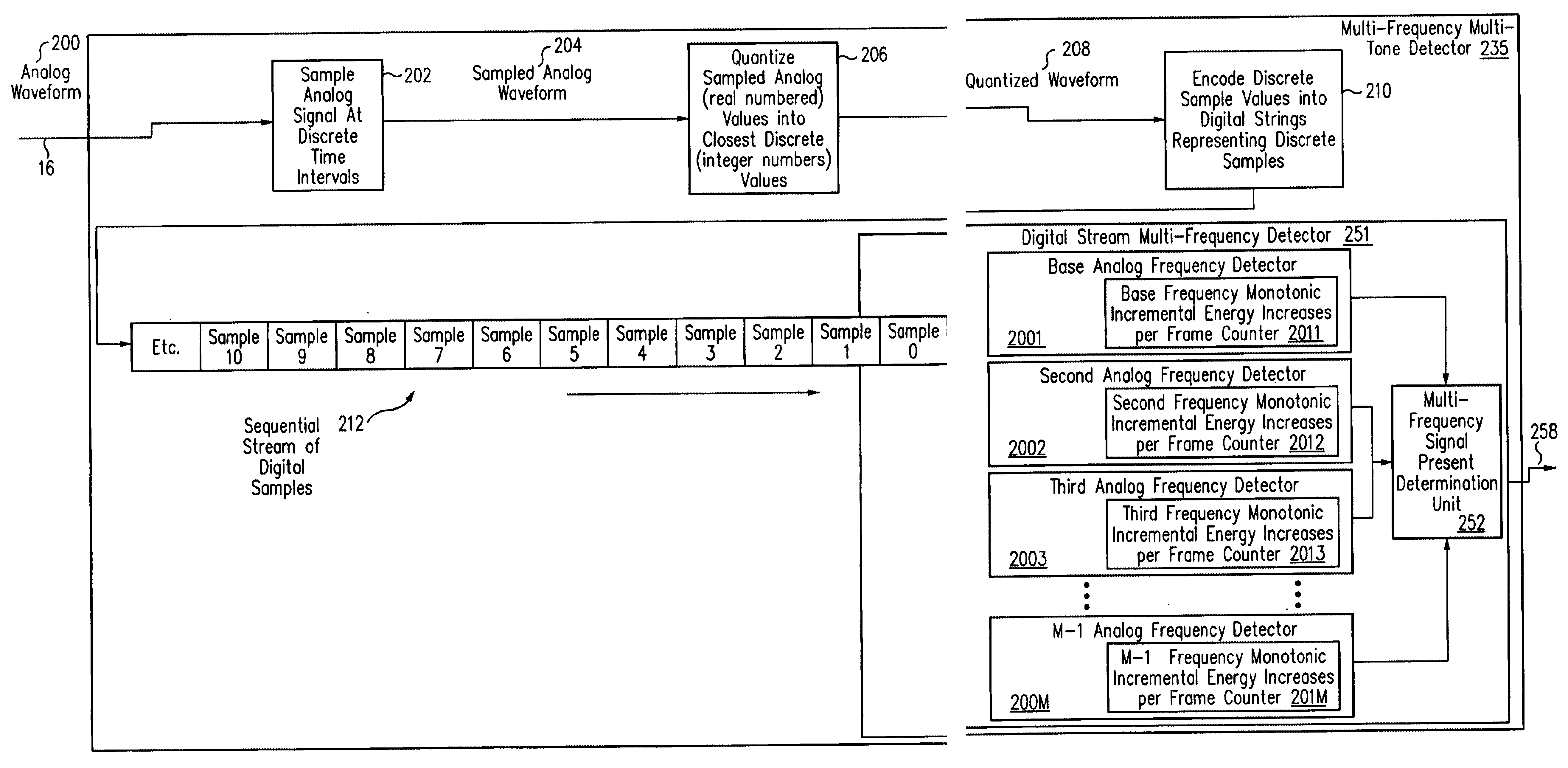
It has been discovered that a method and system can be produced which will substantially maximize the detection of dual tone multi-frequency signals, particularly in an environment where other signals, such as music, speech, data, and noise can be simultaneously present with the dual tone multi-frequency signals. In the method and system, an analog signal is received. A stream of data samples is created from the analog signal. Based on the stream of data samples, a confidence factor regarding the presence of the one or more analog signals is created. The confidence factor is created based upon a confidence factor calculated for each of the one or more analog frequency signals. The confidence factor calculated for each of the one or more analog frequency signals is calculated utilizing incremental energies associated with each of the one or more analog frequency signals.
The foregoing has described embodiments of the present invention methodically. Following are specific examples demonstrating calculations utilized by the dual-frequency embodiment of the present invention to increase the accuracy in determining whether a DTMF signal is actually present.

Problems solved by technology

A problem which commonly occurs when in-band signaling tones, single or multiple,are used to transmit information, is the accurate estimation of the time duration for which the signal is present.
Detection of such signals in environments where noise or speech is present is generally recognized to be a complex issue.
One such complexity involves the issues of talk-off and talk-down.
Talk-down occurs whenever a signal detector erroneously rejects valid DTMF signaling signals due to the presence of competing speech, music or other extraneous background noise.
The existence of these complex signals introduces spectral components into the signal that distort and ultimately impair the detection of valid DTMF signaling tones.
Since the CO did not originate the alerting signal, the far-end party will unintentionally receive the acknowledgment signal at an undesirable listening level.
In both cases, detector failure degrades the quality of the service.
Therefore, during this time, the detector is constantly exposed to speech with the consequent possibility of talk-off.
As has been discussed, the phenomena of talk-off and talk-down have deleterious effects upon communication efficiency.
As has also been discussed, the cause of the talk-off and talk-down phenomena is the inability to accurately the detect the presence of DTMF signals in a noisy environment.

Method used


Image

  • Method and system for improved analog signal detection
  • Method and system for improved analog signal detection
  • Method and system for improved analog signal detection

Examples


example 2

Referring now to FIGS. 14A, 14B, and 14C, which are a screen captures of a simulation of an embodiment of the present invention, shown are frame and sub-frame interval energies. Example 2 illustrates the usefulness of the energy-increase counts when the detector is running in the presence of speech only. Here, the simulated speech level is -12 dBm and FIG. 14A shows that the speech is at a moderately high level. FIGS. 14B and 14C are the energy outputs from the 2130 Hz and 2750 Hz detectors respectively.

In FIG. 14C, it can be seen that sub-frame (-1) of the 2750 detector indicates that this could be the start sub-frame of a possible CAS tone: the final sub-frame energy is high and it has 3 linearly increasing energy values at 96, 125 and 160 samples. However, the absence of energy in the 2130 detector disallows this sub-frame since both tones must be present simultaneously and meet the power differential of + / -6 dBs between the tones. However, if one examines the next 4 sub-frames, ...

example 3

Examination of FIGS. 15A and 15B, which are a screen captures of a simulation of an embodiment of the present invention, shown are frame and sub-frame interval energies. These figures illustrate the usefulness of these energy-increase counts when the detector is detecting a CAS tone in the presence of moderately high speech levels. Again, the speech signal level is -12 dBm, as in FIG. 14A. In FIG. 15A, it can be seen that the final energy detection for the 2130 Hz tone in frame 3 is negligible and, in consequence, the power differential of + / -6 dBs between the tones is not met. Also, the power differential in frame 1 is also outside the required value. Since the energy outputs from the detector should be the same as those in FIG. 13, where the input signal to the detector was a CAS tone at -32 dBm with a duration of 80 ms, it can be seen that the presence of speech has disrupted the detection process. The actual figures for the detector are shown in Table 5 below:

Thus, if the final ...


PUM


Abstract

A method and system for improved detection of analog signals, where the analog signals may be composed of one or more analog frequencies. In the method and system, an analog signal is received. A stream of data samples is created from the analog signal. Based on the stream of data samples, a confidence factor regarding the presence of the one or more analog signals is created. The confidence factor is created based upon a confidence factor calculated for each of the one or more analog frequency signals. The confidence factor calculated for each of the one or more analog frequency signals is calculated utilizing incremental energies associated with each of the one or more analog frequency signals.

Description

1. Field of the InventionThe present invention relates to analog communication systems. In particular, the present invention relates to analog communication systems, such as telephony systems, wherein analog control signals are sent in voice band.2. Description of the Related ArtAn analog communication system is a communication system wherein information is transmitted as a continuous-time signal. One such analog communication system is an analog telephony system.Within analog telephony systems, it is necessary for communication system control information to be transmitted between communications devices. Such information can be used to control switching, to alert a telephone user that he or she has a call waiting, or to display caller identification information. One way in which such control information is transmitted within telephony systems is referred to as "in-band signaling."In an analog telephony system, analog electrical signals utilized within the telephony system are direct...

Claims


Application Information

Patent Timeline
Patent Type & Authority Patents(United States)
IPC IPC(8): H04L27/30H04L27/00H04L27/26
CPCH04L27/30H04L27/0012
Inventor BARTKOWIAK, JOHN G.
Owner MICROSEMI SEMICON U S
Why Eureka
Try Eureka