Fastening a CMC combustion chamber in a turbomachine using the dilution holes

a technology of combustion chamber and turbomachine, which is applied in the direction of machines/engines, efficient propulsion technologies, light and heating apparatus, etc., can solve the problems of inconvenient use of metal combustion chambers, large differences in thermal expansion coefficients between metal materials and composite materials, etc., to achieve significant weight saving, reduce the size of the connection, and simplify the effect of connection

Inactive Publication Date: 2003-12-30
SN DETUDE & DE CONSTR DE MOTEURS DAVIATION S N E C M A
View PDF12 Cites 82 Cited by
  • Summary
  • Abstract
  • Description
  • Claims
  • Application Information

AI Technical Summary

Benefits of technology

The present invention mitigates those drawbacks by proposing a mount for the combustion chamber within the casings, which mount has the ability to absorb the displacements induced by the different expansion coefficients of these parts. Another object of the invention is to propose a mount which makes best use of the existing characteristics of the combustion chamber.
These objects are achieved by a turbomachine comprising inner and outer annular shells of metal material containing, in a gas flow direction F: a fuel injection assembly; an annular combustion chamber of composite material having a longitudinal axis and a plurality of oxidizer feed orifices; and an annular nozzle of metal material having fixed blades and forming the inlet stage of a high pressure turbine, wherein said combustion chamber of composite material is held in position between said inner and outer annular metal shells by a plurality of flexible metal tongues, first ends of said tongues being interconnected by respective metal rings fixed securely to each of said inner and outer annular metal shells by first fixing means, and second ends of said tongues being fixed securely to said composite material combustion chamber via at least a fraction of said oxidizer feed orifices by second fixing means, the flexibility of said fixing tongues serving, at high temperatures, to accommodate free displacement in radial and axial directions between said composite material combustion chamber and said inner and outer annular metal shells. The oxidizer feed orifices are constituted by holes for feeding air to a primary zone and / or a dilution zone of said combustion chamber.
With this particular fixed connection structure, the various kinds of wear due to contact corrosion in prior art systems can be avoided. Using the primary holes or the dilution holes (depending on the intended chamber configuration) as anchor points also serves to simplify the connection considerably and to reduce the size thereof. In addition, the presence of flexible tongues taking the place of traditional flanges makes it possible to achieve an appreciable weight saving. Because of their flexibility, these tongues make it easy to accommodate the expansion difference that appears at high temperatures between metal parts and composite parts (by accommodating the displacements due to expansion) while continuing to hold the combustion chamber and keep it properly centered within the annular shells.

Problems solved by technology

Nevertheless, under certain particular conditions of use, implementing very high combustion temperatures, using a metal combustion chamber turns out to be entirely inappropriate from a thermal point of view and it is necessary to use a chamber based on high temperature composite materials of the CMC type.
However, the difficulties of working such materials and their raw materials costs mean that their use is generally restricted to the combustion chamber itself, with the inlet nozzle of the high pressure turbine and the inner and outer shells containing the chamber then continuing to be made more conventionally out of metal materials.
Unfortunately, metal materials and composite materials have coefficients of thermal expansion that are very different.
This gives rise to particularly severe problems of connection with the inner and outer shells and at the interface with the inlet nozzle to the high pressure turbine.

Method used


Image

  • Fastening a CMC combustion chamber in a turbomachine using the dilution holes
  • Fastening a CMC combustion chamber in a turbomachine using the dilution holes
  • Fastening a CMC combustion chamber in a turbomachine using the dilution holes

Examples


first embodiment

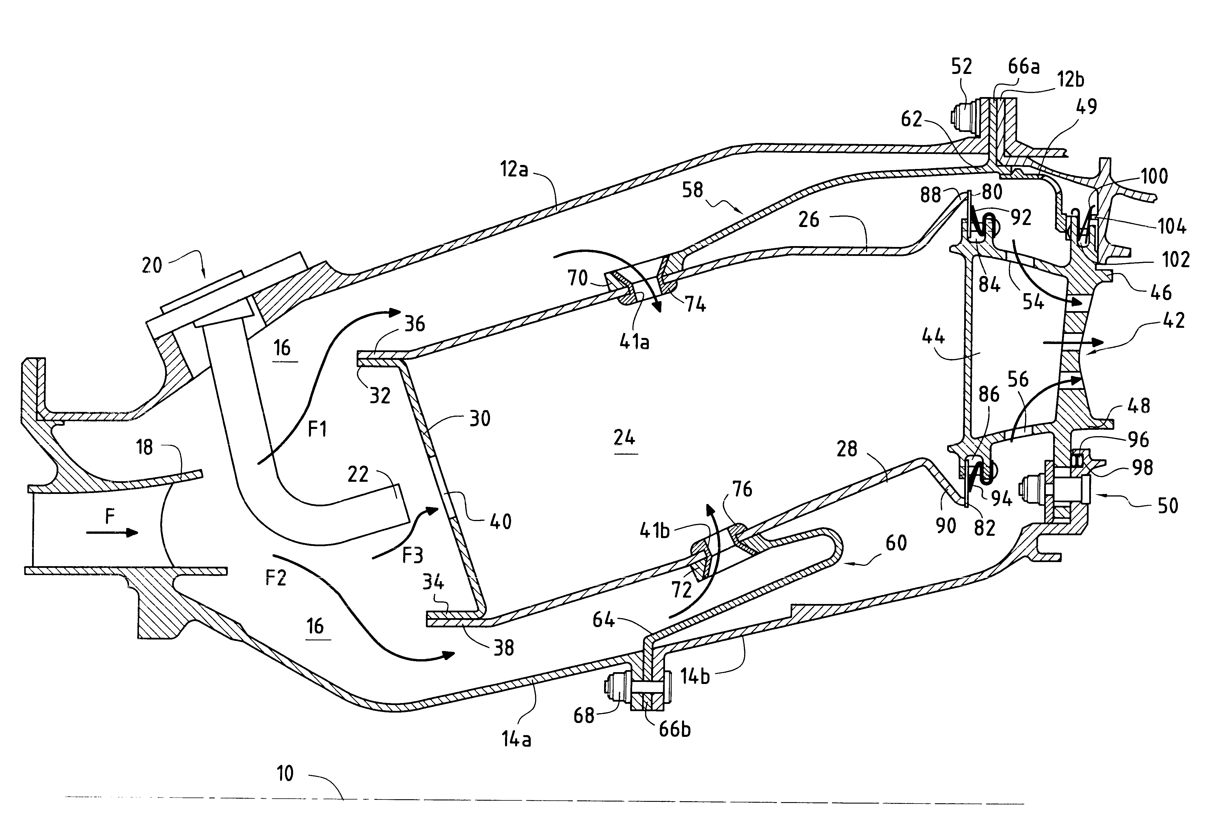
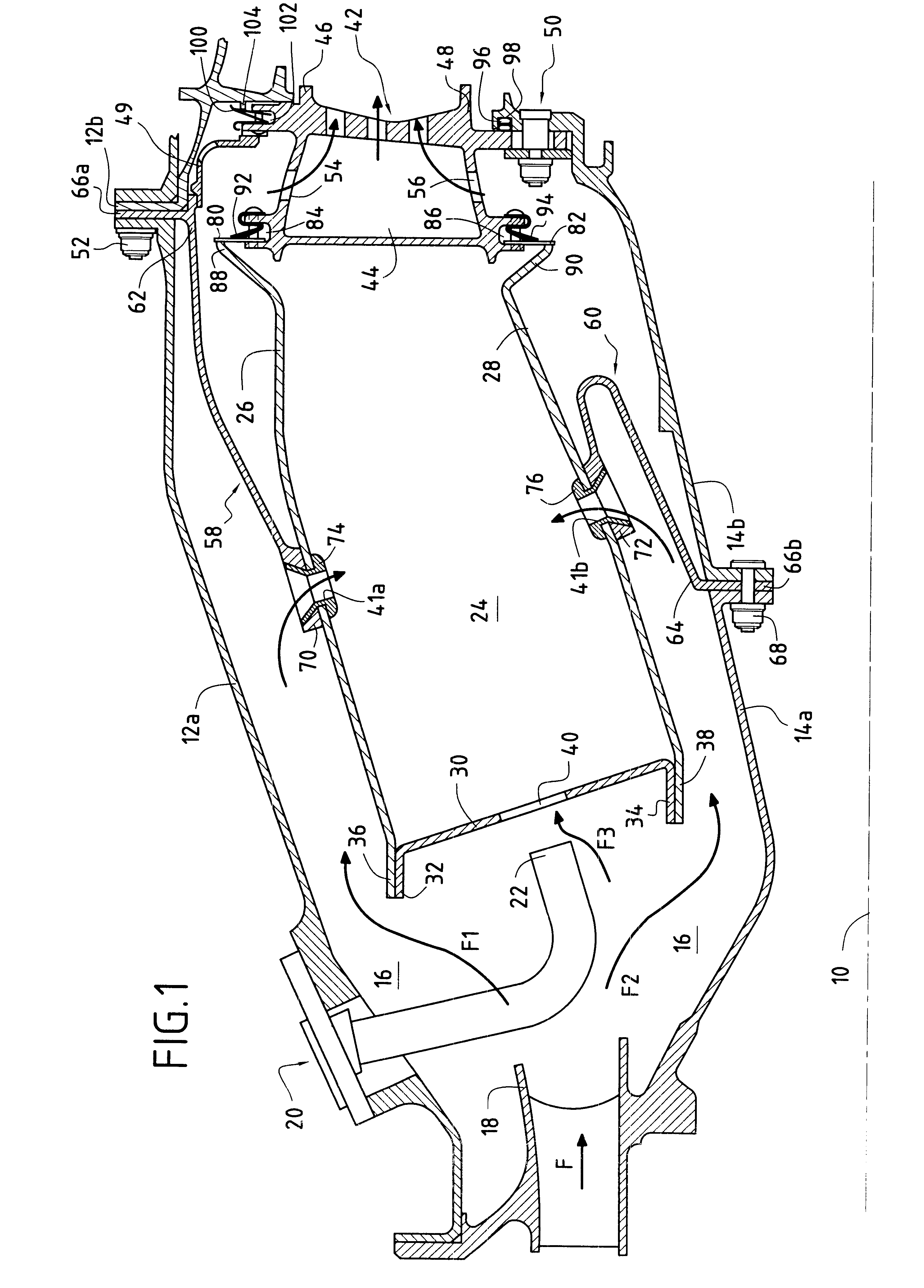
FIG. 1 shows the invention in which the vertices 70, 72 forming second ends of the tongues are fixed respectively on the outer and inner side walls 26 and 28 of the combustion chamber by being crimped by means of collars 74, 76 inserted from the hearth side of the combustion chamber thorough respective oxidizer feed orifices 41a, 41b and serving to hold the tongue against the combustion chamber wall once crimping has been performed. The real diameter of the feed orifice (dilution hole or primary hole) is matched by the collar whose outer edges (on the hearth side of the chamber) are rounded so as to avoid catching flames.

The bases 62, 64 forming first ends of the tongues as interconnected by the ring 66a, 66b are preferably held between existing flanges for connecting together the upstream and downstream portions of the inner and outer annular shells 14a, 14b and 12a, 12b, and are held securely by fixing means 52, 68, preferably of the bolt type.

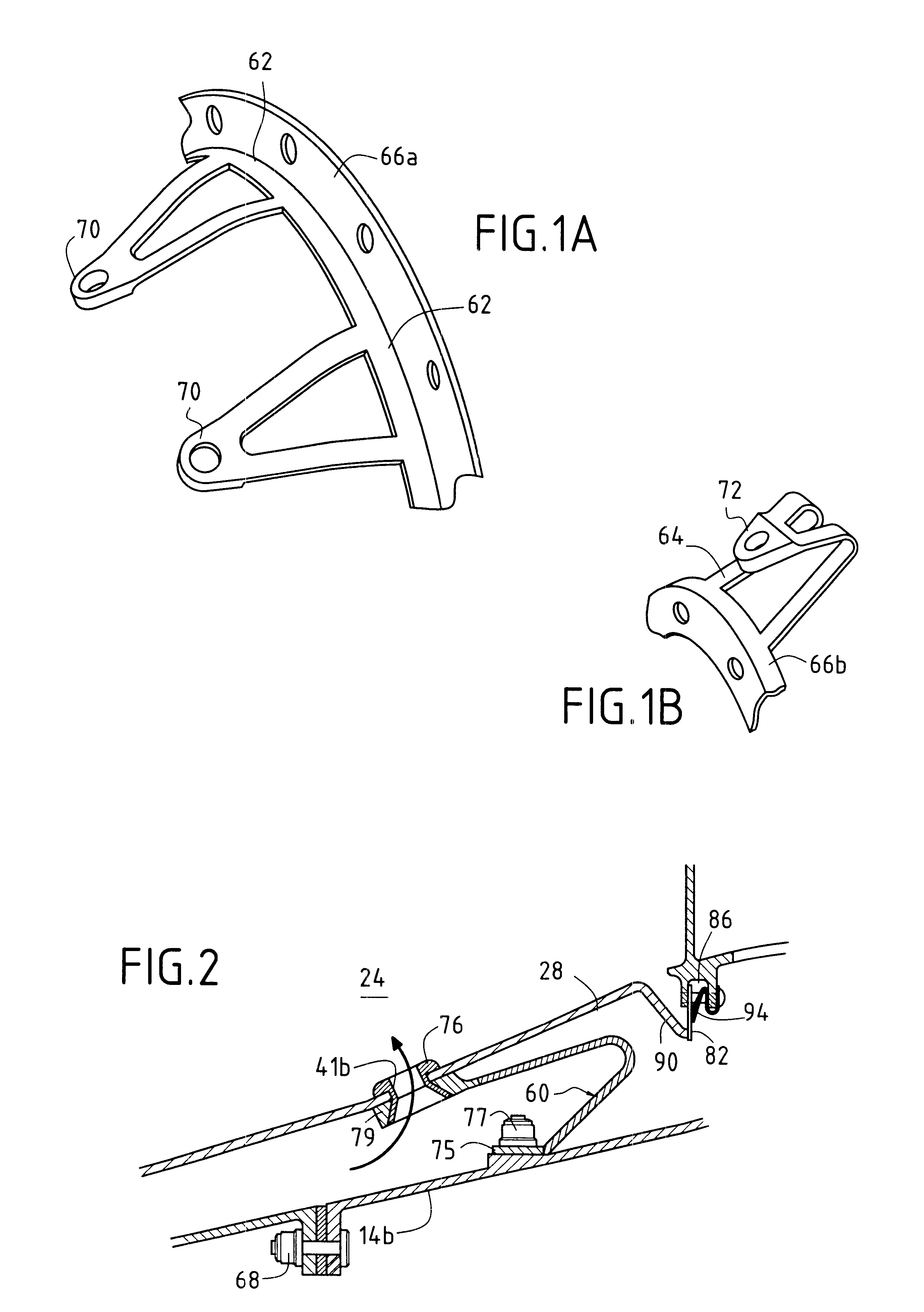
In a variant shown in FIG. 2, the ton...

second embodiment

In the invention, as shown in FIG. 3, the second ends of the tongues 70, 72 are fixed respectively to the outer and inner side walls 26, 28 of the combustion chamber via inserts each comprising two coaxial portions fixed to each other (advantageously by brazing or welding), one comprising a collar 74a, 76a pressed against the hearth side of the wall and the other in the form of a ring 74b, 76b surrounding the collar and pressing the eyelet-forming second end of the tongue against the wall. As in the preceding embodiment, the real diameter of the dilution hole or of the primary hole is taken up by the collar whose outer edges are rounded so as to avoid catching flames.

Advantageously, the tongue 58 can have an opening 58a formed close to the second end 70 of the tongue in register with the injection orifice 41a so as to make it easier to feed after assembly. In addition, in the example shown, the first ends of this tongue are no longer welded to a ring mounted between flanges (as show...


PUM


Abstract

In a turbomachine comprising inner and outer annular shells of metal material containing, in a gas flow direction F: a fuel injection assembly; an annular combustion chamber of composite material having a plurality of air feed orifices in a primary zone and / or in a dilution zone; and an annular nozzle of metal material forming the inlet stage with fixed blades for a high pressure turbine, provision is made for the combustion chamber to be held in position between the inner and outer annular metal shells by means of a plurality of flexible metal tongues having first ends interconnected by respective metal rings fixed securely to said inner and outer annular shells by first fixing means, and second ends fixed securely to the composite material combustion chamber at it air feed orifices by second fixing means.

Description

The present invention relates to the specific field of turbomachines, and more particularly it relates to the problem posed by mounting a combustion chamber made of ceramic matrix composite (CMC) type material in the metal chamber casings of a turbomachine.PRIOR ARTConventionally, in a turbojet or a turboprop, the high pressure turbine (HPT) and in particular its inlet nozzle, the combustion chamber, and the inner and outer shells (or casings) of said chamber are all made of the same material, generally a metal. Nevertheless, under certain particular conditions of use, implementing very high combustion temperatures, using a metal combustion chamber turns out to be entirely inappropriate from a thermal point of view and it is necessary to use a chamber based on high temperature composite materials of the CMC type. However, the difficulties of working such materials and their raw materials costs mean that their use is generally restricted to the combustion chamber itself, with the inl...

Claims


Application Information

Patent Timeline
Patent Type & Authority Patents(United States)
IPC IPC(8): F23R3/06F23R3/60F23R3/00F23R3/04F02C7/00F23R3/42F23R3/44
CPCF23R3/007F23R3/60F23R3/06F05B2230/606Y02T50/675Y02T50/60
Inventor CALVEZ, GWENAELLEHERNANDEZ, DIDIERFORESTIER, ALEXANDRE
Owner SN DETUDE & DE CONSTR DE MOTEURS DAVIATION S N E C M A
Why Eureka
Try Eureka