
Optical amplifier transient control apparatus

a transient control and optical amplifier technology, applied in electrical devices, fibre transmission, laser details, etc., can solve the problems of poor performance of analog circuits measuring voltage ratios, noise and inaccurate pump power level setting, and severe problems

Inactive Publication Date: 2004-01-13
CIENA
View PDF4 Cites 22 Cited by
  • Summary
  • Abstract
  • Description
  • Claims
  • Application Information

AI Technical Summary

Problems solved by technology

As the input power approaches zero, however, severe problems arise because of the division by zero problem, see equation A) below.
While it is possible to compensate for this division by zero problem by switching to other equations when the input power (Pin) approaches zero, a discontinuity at the switchover point may occur which can cause noise and an inaccurate pump power level setting.
Furthermore, such conventional constant gain control schemes use digital implementations because of the difficulty in measuring gain in analog circuitry.
This difficulty partially stems from the very poor performance of analog circuits measuring voltage ratios.
Both issues apply for very low or zero inputs.

Method used


Image

  • Optical amplifier transient control apparatus
  • Optical amplifier transient control apparatus
  • Optical amplifier transient control apparatus

Examples


Embodiment Construction

The following detailed description of the invention refers to the accompanying drawings. The same reference numbers in different drawings identify the same or similar elements. Also, the following detailed description does not limit the invention. Instead, the scope of the invention is defined by the appended claims and equivalents thereof.

The expression "optically communicates" as used herein refers to any connection, coupling, link or the like by which optical signals carried by one optical system element are imparted to the "communicating" element. Such "optically communicating" devices are not necessarily directly connected to one another and may be separated by intermediate optical components or devices. Likewise, the expressions "connection" and "operative connection" as used herein are relative terms and do not require a direct physical connection.

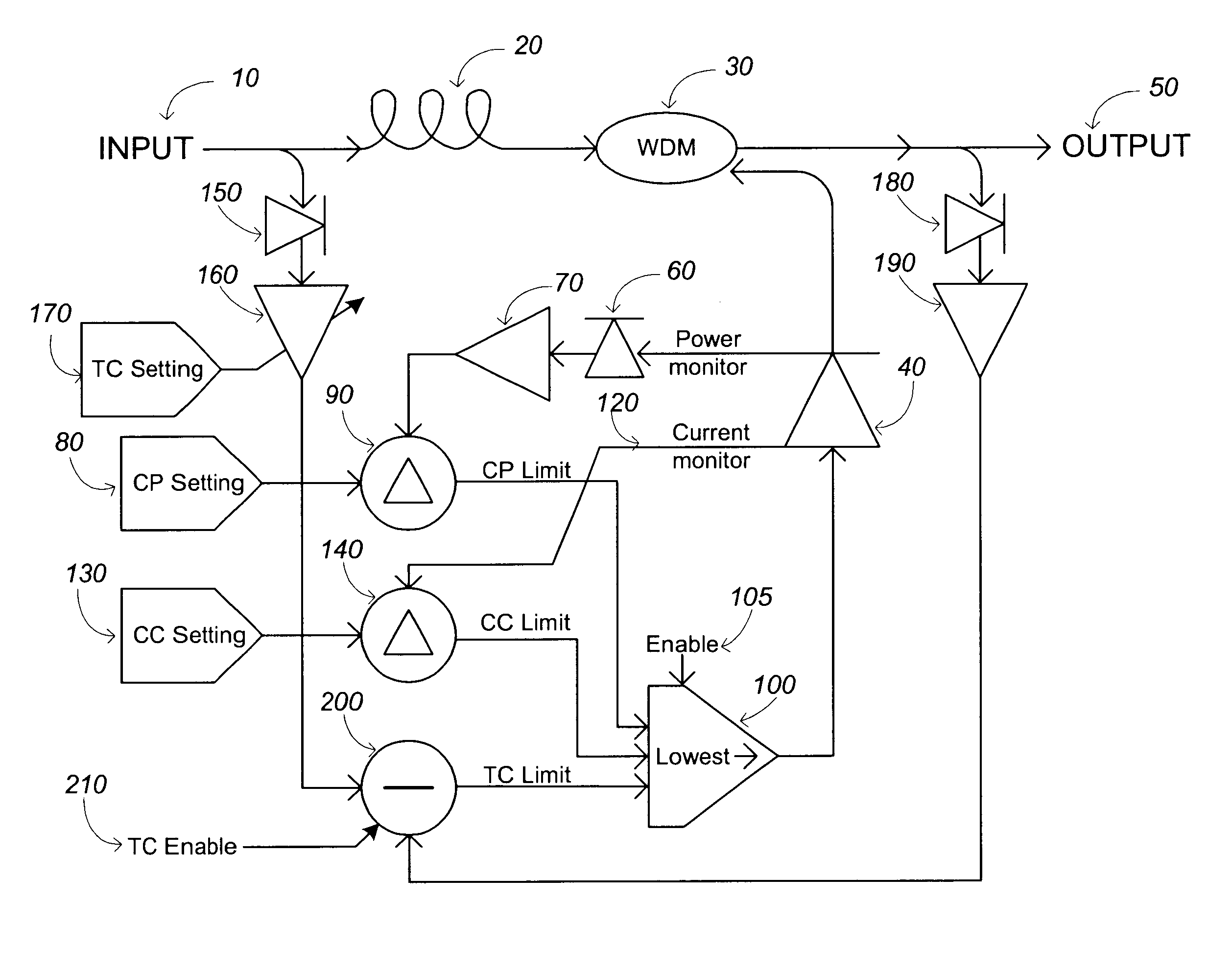
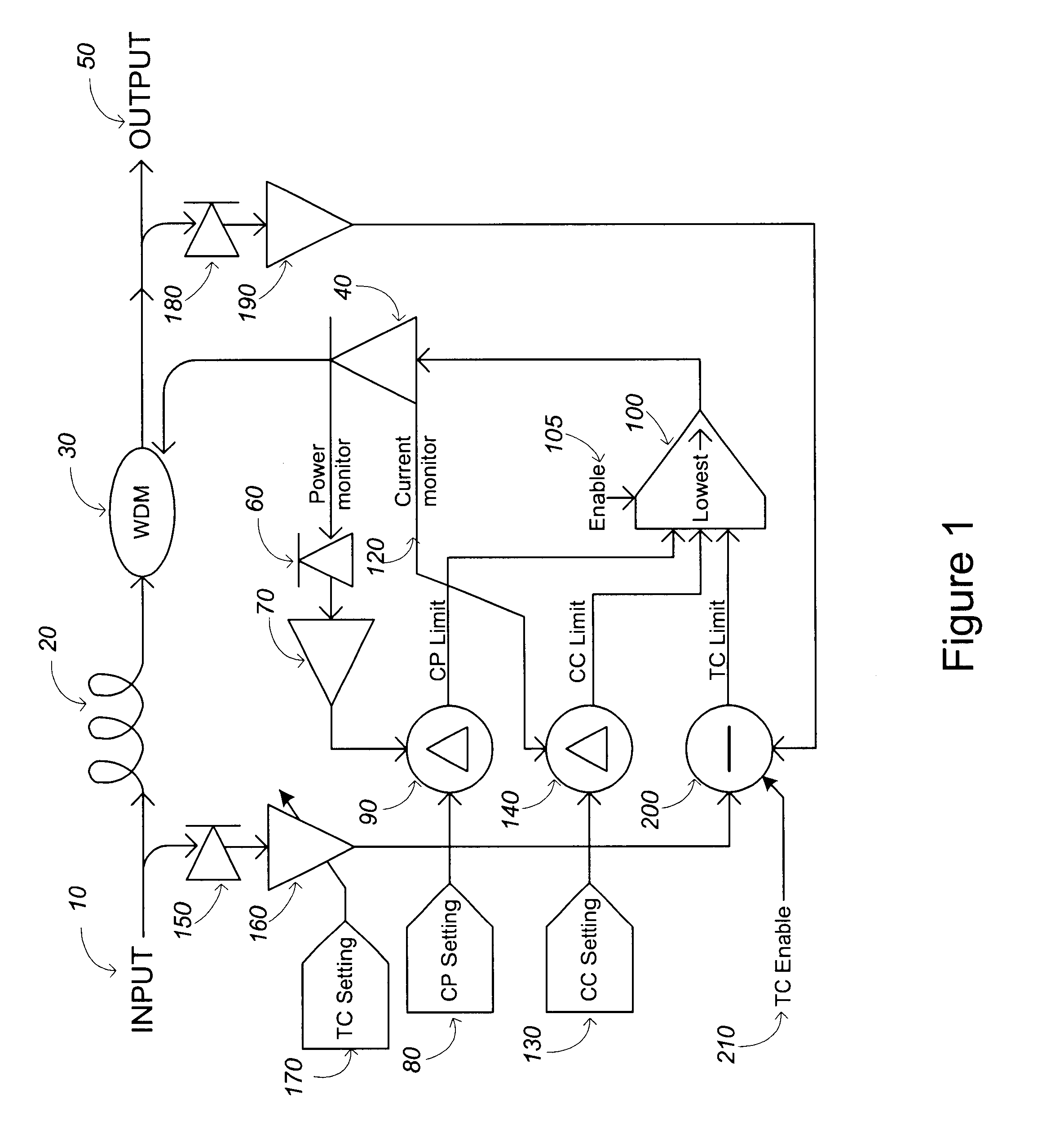
FIG. 1 illustrates a conventional single stage fiber amplifier including a segment of doped fiber 20 doped with an optically activ...


PUM


Abstract

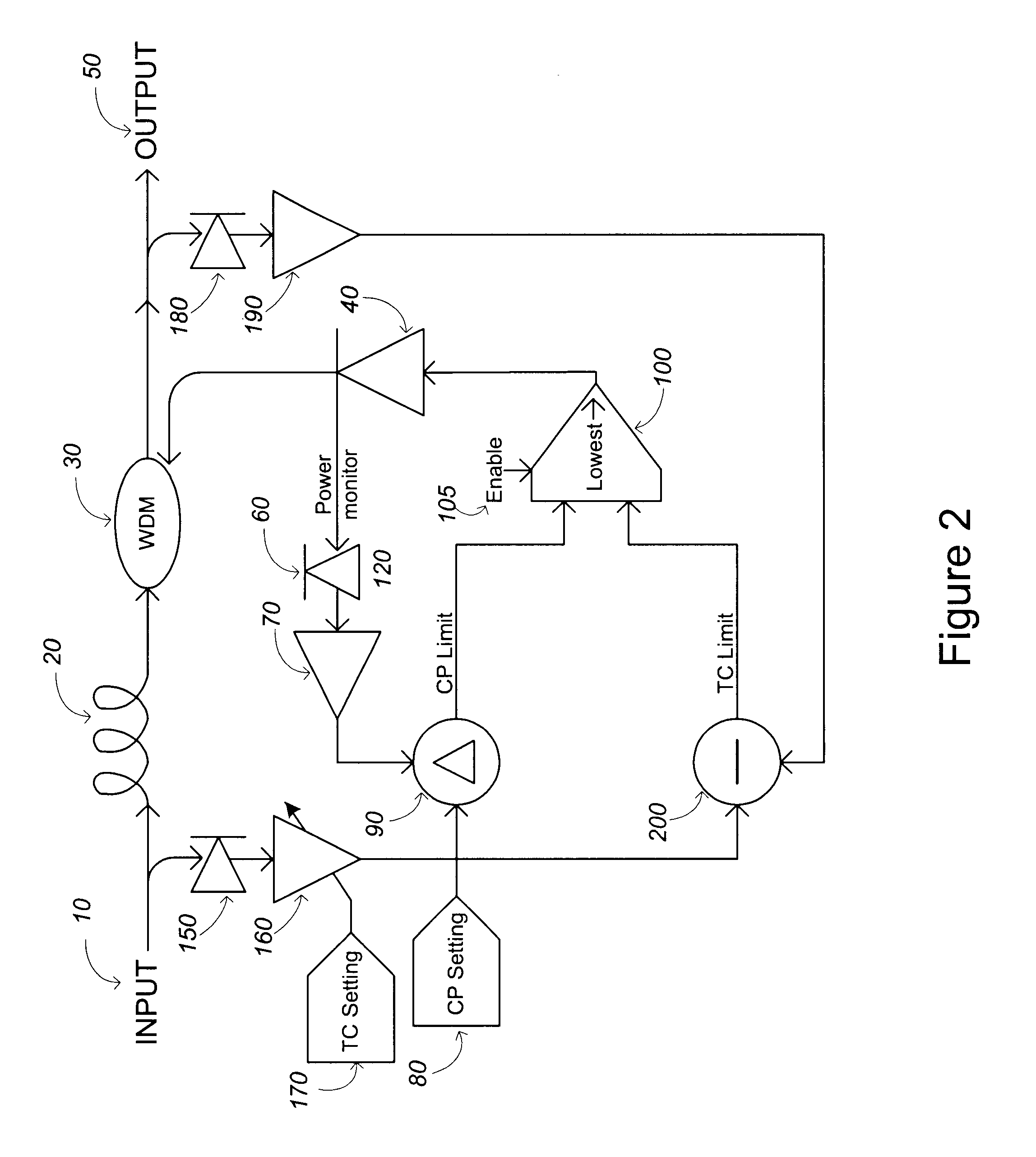
An optical amplifier control circuit and method controls transients and avoids the problems associated with measuring gain. The input power level is detected and amplified by a transient control setting to provide a desired gain value against which is compared the output power level. This transient control error may be used in conjunction with a constant power error and / or a constant current error such that the lowest of the error values is used to drive the pump laser. Current and power feedback signals and settings are used to derive the error values. Multiple pump lasers per stage may also be controlled and a multi-stage amp having a cascaded structure may be realized using the inventive techniques.

Description

1. Field of InventionThe invention generally relates to controlling an optical amplifier. More particularly, the invention relates to circuits and apparatuses that control optical amplifiers having a fiber segment doped with an optically active material.2. Description of Related ArtA variety of techniques have been employed to control optical amplifiers. One such conventional technique is the constant gain control loop. The conventional constant gain control loop is simple: measure the input and output powers and calculate the gain based on the input (Pin) and output (Pout) power measurements (measured gain=Pout / Pin). Changes are then made to the amplifier pump power such that the measured gain achieves the pre-stored or target gain value. In this way, it is possible to control the amplifier module to have a constant gain value regardless of changes to the input power level such as when optical WDM (wavelength division multiplexed) channel(s) are added or dropped.In other words, tra...

Claims


Application Information

Patent Timeline
IPC IPC(8): H01S3/00
CPCH04B10/296H01S3/06754H01S3/06758H01S3/10015H01S3/1301H01S3/1305H01S3/13013
Inventor STUMMER, ALANBAO, JUN
Owner CIENA
Learn More