Phase locked loop with offset cancellation

a phase locked loop and offset cancellation technology, applied in the direction of electrical equipment, pulse automatic control, etc., can solve the problems of high cost of wideband fet input op-amps, difficulty in smoothly switching between wideband and narrowband tracking modes,

Inactive Publication Date: 2004-01-20
NORTHROP GRUMMAN SYST CORP
View PDF6 Cites 41 Cited by
  • Summary
  • Abstract
  • Description
  • Claims
  • Application Information

AI Technical Summary

Problems solved by technology

The speed with which the phase locked loop can transition from one lock point (or frequency) to the next is a limiting performance factor in many applications.
However, construction of an active integrator typically requires the use of a wideband operational amplifier to provide a sufficiently large PLL bandwidth.
Operating with offset phase may cause undesirable effects such as increased spurious energy from the phase detector or difficulty in smoothly switching between wideband and narrowband tracking modes.
However, wideband FET input op-amps are very expensive.
However, bipolar input op-amps universally have large input bias currents and at least modest offset voltages which result in operating with offset phase.

Method used


Image

  • Phase locked loop with offset cancellation
  • Phase locked loop with offset cancellation
  • Phase locked loop with offset cancellation

Examples


Embodiment Construction

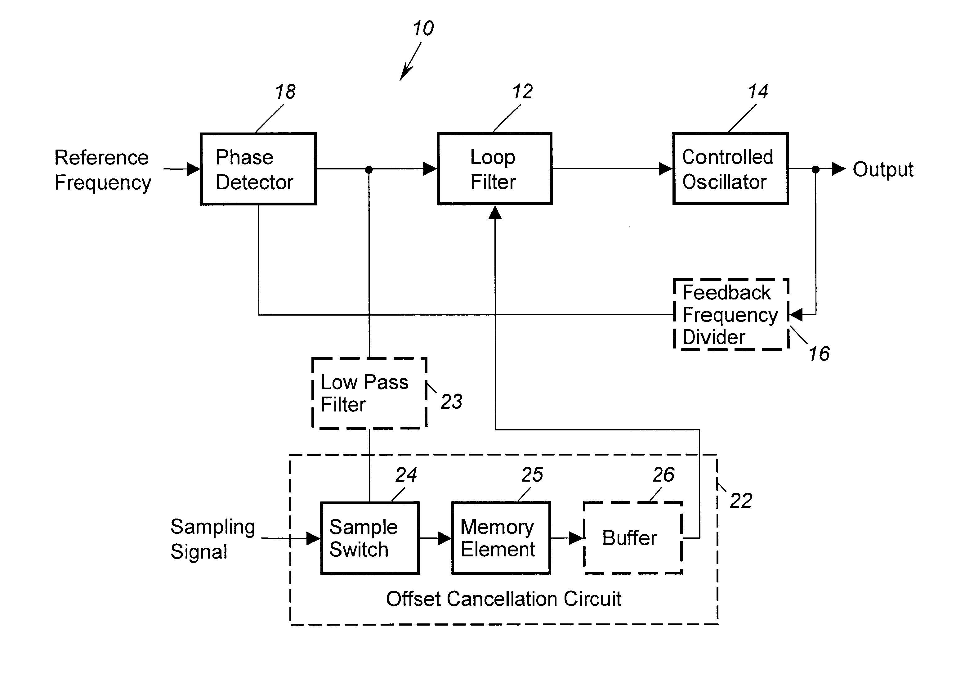
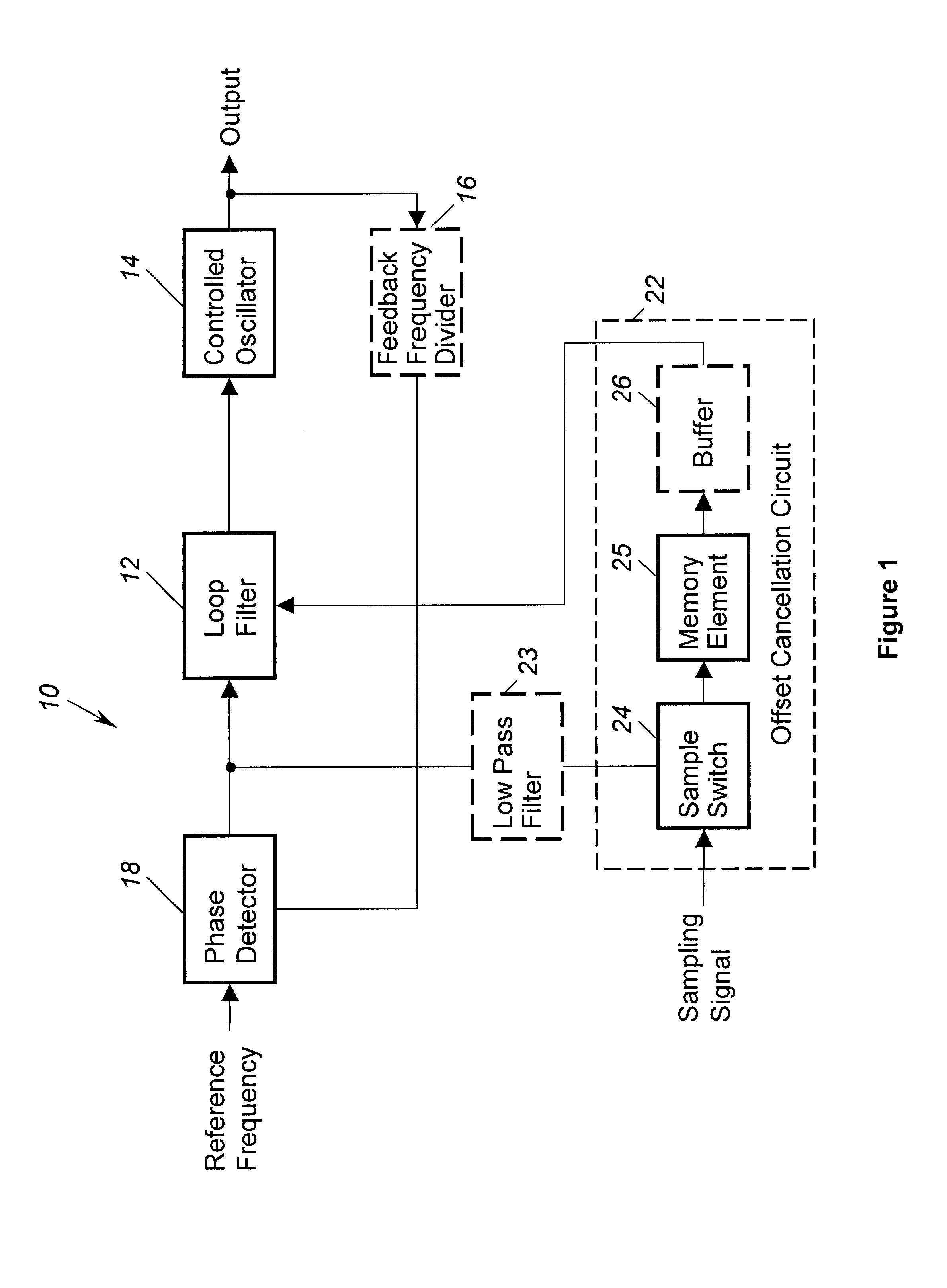
Referring to FIG. 1, a phase locked loop 10 according to the present invention is shown. The PLL 10 includes a controlled oscillator 14 for generating an output frequency signal in response to a tuning signal. A feedback frequency divider 16 is preferably included, although not required since the PLL 10 is not limited to circuits that are capable of switching frequencies. The feedback frequency divider 16 senses the output frequency signal and generates a divided frequency signal. A phase detector 18 compares the frequency and phase of the divided frequency signal to the frequency and phase of a reference frequency signal and generates an error signal to represent the difference between the reference frequency signal and the divided frequency signal. A loop filter 12 coupled to the phase detector 18 generates the tuning signal from the error signal. The loop filter 12 attenuates injected noise and removes high frequency components that are present in the error signal. The loop filte...


PUM


Abstract

A phase locked loop (10) for generating a variable output frequency signal. The phase locked loop (10) includes a controlled oscillator (14) to generate the variable output frequency signal in response to a tune signal. A phase detector (18) is activable in response to a gating signal (20) to generate an error signal representing a difference between a reference frequency signal and the variable output frequency signal. A loop filter (12) having a filter characteristic, filters the error signal and generates the tune signal. An offset cancellation circuit (22) is coupled to the loop filter (12). In response to an error signal representing phase offset of the phase locked loop (10), the offset cancellation circuit (22) supplies a compensating signal to reduce the phase offset.

Description

1. Field of the InventionThe present invention relates generally to phase locked frequency synthesizers, and in particular to phase locked loops that suppress the leakage of spurious energy, phase locked loops that switch bandwidth, or phase locked loops that require low phase offset.2. Discussion of the Related ArtA phase locked loop (PLL) is a negative feedback system that maintains a constant phase and zero frequency difference between a variable frequency and a reference frequency. Conventional PLL's include a phase detector element to compare the frequency and phase of an oscillator to that of the reference frequency. The oscillator is then controlled to maintain the constant phase and frequency difference.The speed with which the phase locked loop can transition from one lock point (or frequency) to the next is a limiting performance factor in many applications. The phase locked loop is therefore often designed with two or more control system bandwidths (or loop transfer funct...

Claims


Application Information

Patent Timeline
Patent Type & Authority Patents(United States)
IPC IPC(8): H03L7/08H03L7/093H03L7/16H03L7/18
CPCH03L7/093H03L7/18
Inventor FISCHER, GERALD R.ALLEN, TALLEY J.TSAI, KEN K.
Owner NORTHROP GRUMMAN SYST CORP
Why Eureka
Try Eureka