

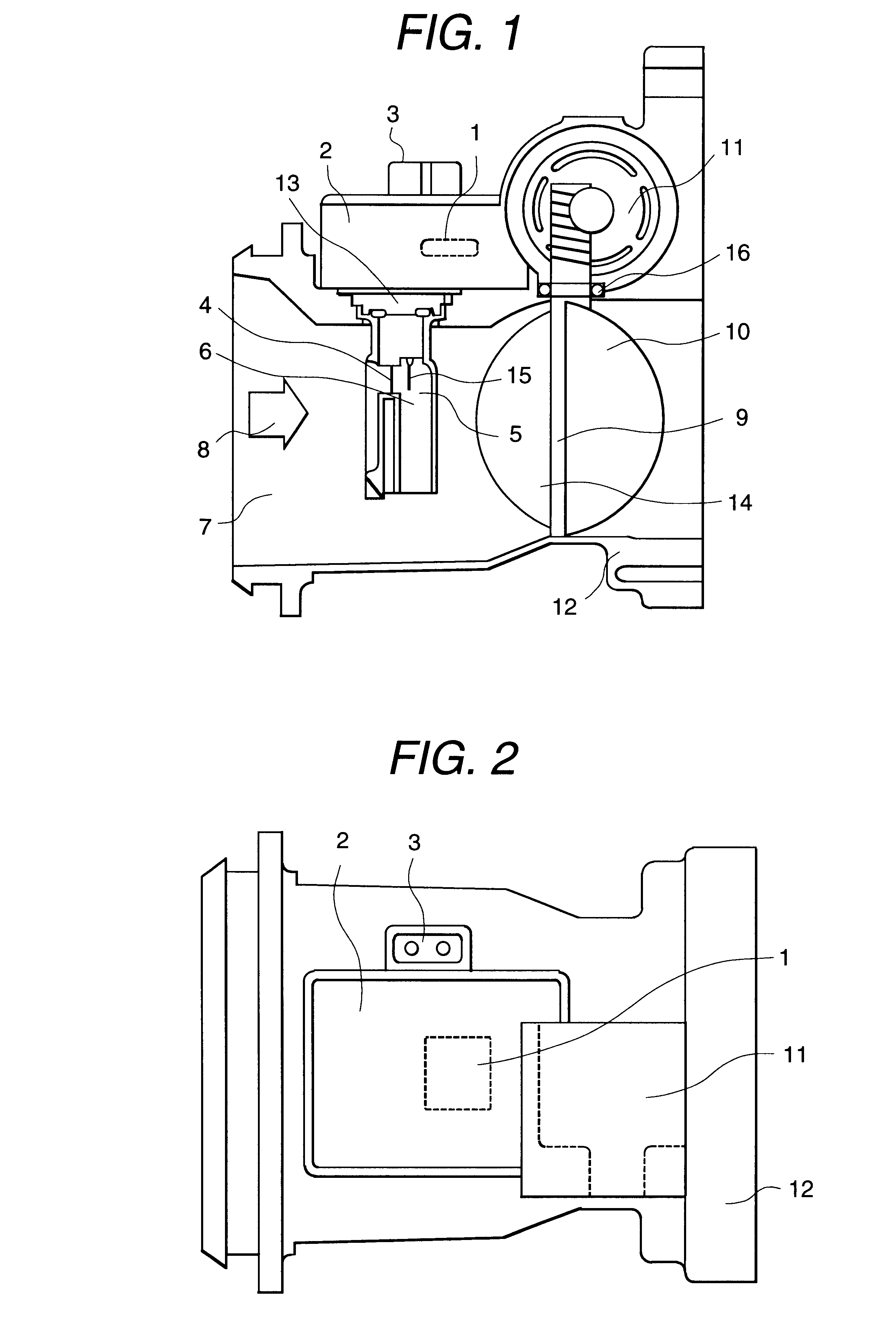
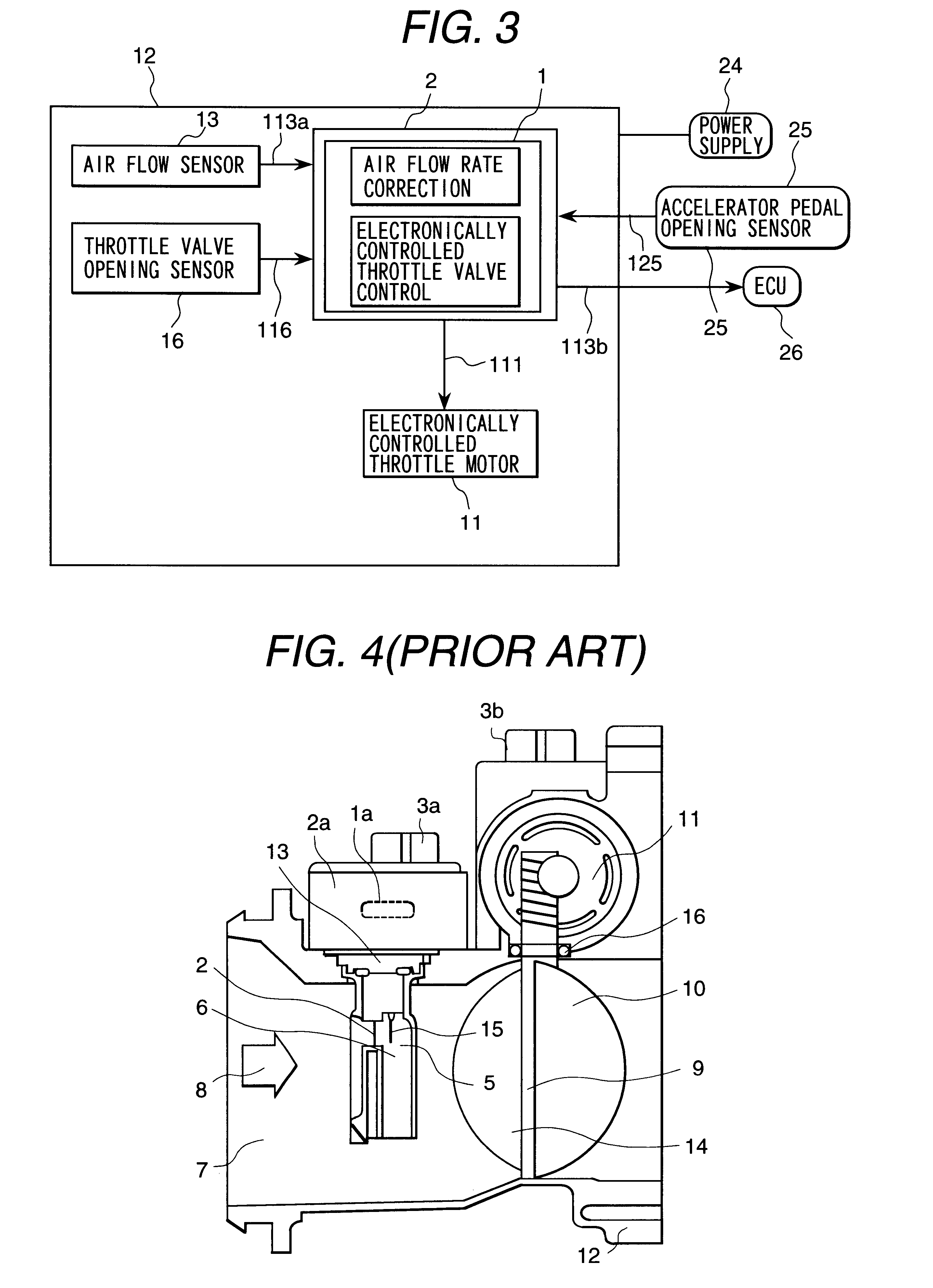
Air flow measuring device formed integrally with electronically controlled throttle body
a technology of air flow measurement and electronically controlled throttle body, which is applied in the direction of electric control, instruments, machines/engines, etc., can solve the problems of wiring and a lot of power supply becoming unnecessary
- Summary
- Abstract
- Description
- Claims
- Application Information
AI Technical Summary
Benefits of technology
Problems solved by technology
Method used
Image


Examples
case 1
In case 1, because the all values of Qafs, QNp, and Q.alpha.N are in correction-unnecessary ranges 213, Qafs is used as the representative value for the controlled variable operation. Neither the correction nor the breakdown judgment are performed. In case 2, the correction value of QN.rho. is calculated because QN.rho. indicates the value different from Qafs or Q.alpha.N and it becomes outside the correction-unnecessary range. Here, the correction of QN.rho. shows the example of the correction like becoming the same value as Q.alpha.N which is a value close to QNp among other air flow rate values. However, it is possible to take the mean value of two or the same value as Qafs. Case 3 shows the state that Qafs, QNp, and Q.alpha.N almost become equal again because the correction is added to QN.rho.. If the comparison, the judgment, and the correction is made under the specific condition, it is possible to make the comparison, the judgment, and the correction under the stable conditio...
PUM
 Abstract
Description
Claims
Application Information