Electric power steering apparatus

a technology of electric power steering and electric motor, which is applied in the direction of steering initiation, instruments, vessel construction, etc., can solve the problems of inability to use redundant means of conventional apparatus, brush brush friction no longer negligible,

Inactive Publication Date: 2004-02-03
MITSUBISHI ELECTRIC CORP
View PDF11 Cites 56 Cited by
  • Summary
  • Abstract
  • Description
  • Claims
  • Application Information

AI Technical Summary

Problems solved by technology

In recent years, however, there is a demand for a more comfortable steering feeling to such an extent that friction of the brush is no longer negligible.
For this reason, there is a problem that the redundant means of the conventional apparatus cannot be used.

Method used


Image

  • Electric power steering apparatus
  • Electric power steering apparatus
  • Electric power steering apparatus

Examples


first embodiment

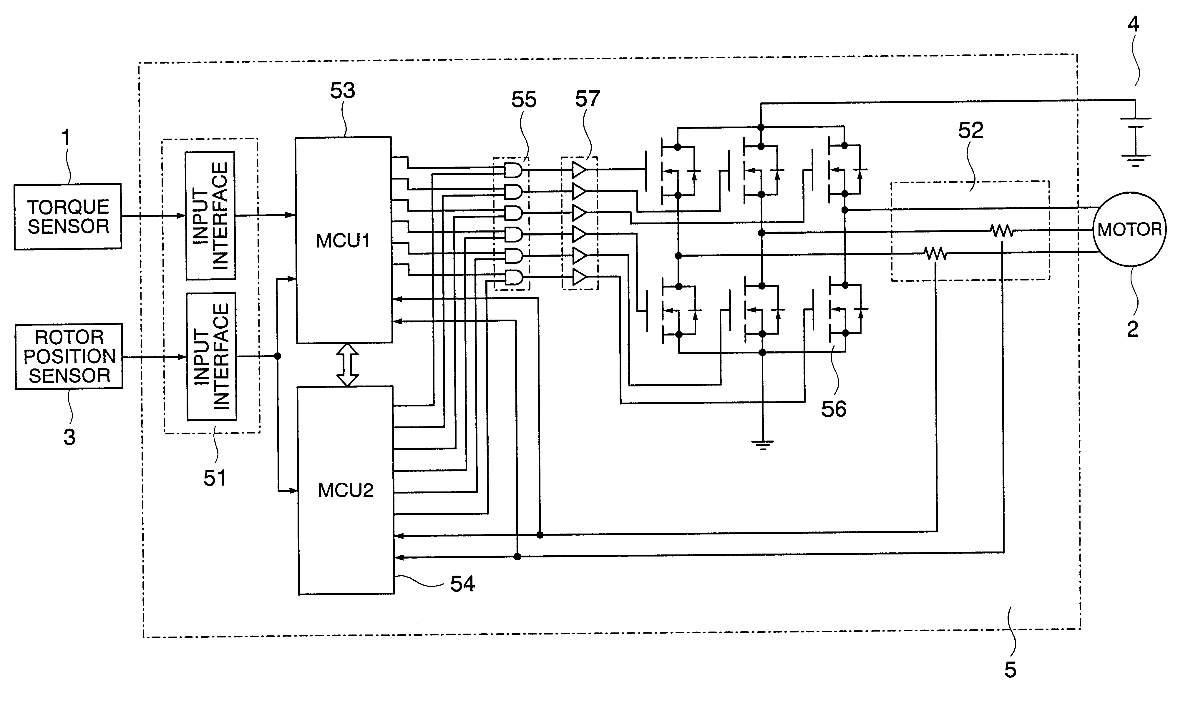
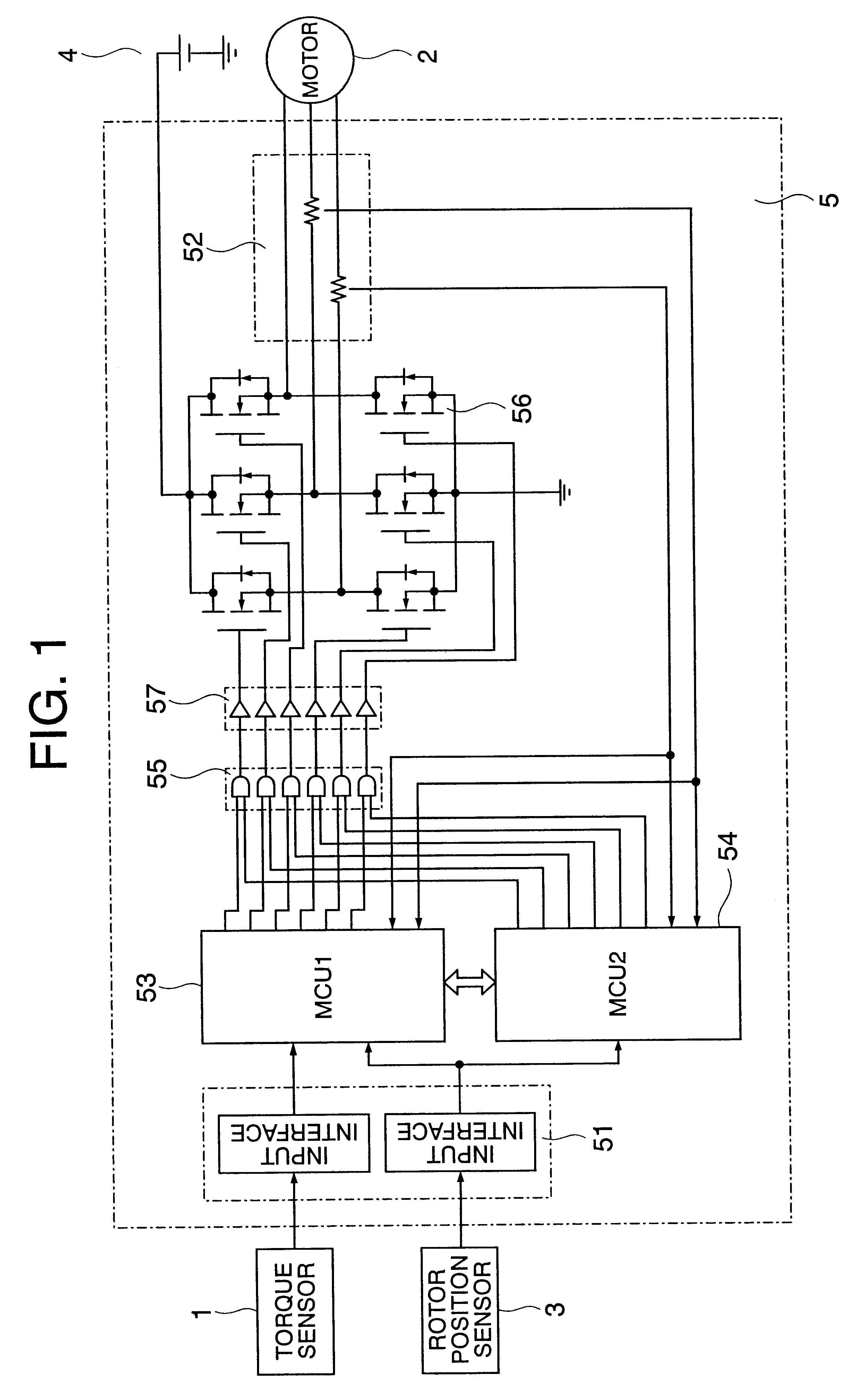
FIG. 1 is a block diagram showing an electric power steering apparatus according to Embodiment 1 of the present invention.

In the diagram, reference numeral 1 denotes a torque sensor to detect steering effort of the driver and reference numeral 2 denotes a motor to assist the steering effort of the driver and a three-phase DC brush-less motor is used here. Reference numeral 3 denotes a rotor position sensor to detect the position of the rotor of the motor 2; 4, a battery to supply power to the motor 2; and 5, a controller to control the motor 2 based on the torque sensor 1.

The following are the components of the controller 5. Reference numeral 51 denotes an input interface circuit for the torque sensor 1 and rotor position sensor 3; 52, a motor current detection circuit that detects a phase current of the motor 2; 53, a first microcontroller (MCU1) as first controlling means for controlling the motor 2 based on the torque sensor 1, rotor position sensor 3 and motor current detection ...

second embodiment

FIG. 7 is a block diagram showing an electric power steering apparatus according to Embodiment 2 of the present invention.

This embodiment shows an example of monitoring the operation more strictly than Embodiment 1 above. Embodiment 2 differs from Embodiment 1 in that the torque sensor 1 is connected to the first microcontroller 53.

FIG. 8 is a functional block diagram to explain a software configuration of this embodiment. In FIG. 8, the input interface circuit 51 in FIG. 7 is omitted and the motor drive circuit 56 and the pre-driver 57 that drives this are expressed as motor drive means.

The operation of this embodiment will be explained based on FIG. 8 below. The parts with the same functions as those in Embodiment 1 above are assigned the same reference numerals and explanations thereof will be omitted. As in the case of Embodiment 1 above, the processing of the first microcontroller 53 can be divided into two blocks; an electric power steering control section 53a and a three-phas...

third embodiment

FIG. 11 is a block diagram showing an electric power steering apparatus according to Embodiment 3 of the present invention. In FIG. 11, the parts with the same functions as those in the Embodiment above are assigned the same reference numerals and explanations thereof will be omitted. As in the case of FIG. 8, in FIG. 11, the input interface circuit 51 is omitted and the motor drive circuit 56 and pre-driver 57 are expressed as motor drive means.


PUM


Abstract

The present invention is an electric power steering apparatus which includes a multi-phase motor that assists steering effort of a driver, a motor drive circuit provided with at least an upper switching element that connects or disconnects the winding of each phase of the multi-phase motor and a power supply, and a lower switching element that connects or disconnects the winding of each phase of the multi-phase motor and grounding, a logic circuit that determines ON / OFF of the upper switching element and the lower switching element, and first and second microcontrollers that control the motor drive circuit via this logic circuit, in which the logic circuit determines ON / OFF of the upper switching element and the lower switching element so that the power to the winding of the each phase of the multi-phase motor is stopped according to the instruction of either the first microcontroller or the second microcontroller.

Description

1. Field of the InventionThe present invention relates to an electric power steering apparatus, and more particularly, to a fail-safe function of electric power steering for automobiles, etc. using a multi-phase motor with three or more phases such as a DC brush-less motor.2. Description of the Prior ArtFIG. 16 is a block diagram showing a conventional electric power steering apparatus disclosed in the Japanese Patent laid-Open no. 1-257674. In FIG. 16, reference numeral 11 denotes a steering torque detector; 12, a torque signal input I / F circuit; 13, a microcomputer (CPU); 14, a motor rightward drive output I / F circuit; 15, a motor leftward drive output I / F circuit; 16, a D / A conversion circuit; 17, a differential amplification circuit; 18, a pulse width modulation circuit; 19, a PWM oscillator (OSC); 20, a motor drive circuit; 20A and 20B, AND circuits; 21, a motor current detection circuit; 22, a resistor; 23A and 23B, output terminals; 24, a motor; 25A and 25B, input terminals; ...

Claims


Application Information

Patent Timeline
Patent Type & Authority Patents(United States)
IPC IPC(8): B62D5/04B62D6/00B62D101/00B62D119/00B62D137/00H02P6/06H02P6/08H02P6/12H02P6/28
CPCB62D5/0463B62D5/0481B62D5/0487B62D5/0493
Inventor KIFUKU, TAKAYUKITSUTSUMI, KAZUMICHIFUJIMOTO, CHIAKI
Owner MITSUBISHI ELECTRIC CORP
Why Eureka
Try Eureka