Flat capacitor for an implantable medical device

Inactive Publication Date: 2004-03-02
CARDIAC PACEMAKERS INC
View PDF74 Cites 178 Cited by
  • Summary
  • Abstract
  • Description
  • Claims
  • Application Information

AI Technical Summary

Benefits of technology

Another aspect of the present invention includes various implantable medical devices, such as pacemakers, defibrillat

Problems solved by technology

When the bursts of electric current are properly sized and timed, they restore normal heart functio

Method used


Image

  • Flat capacitor for an implantable medical device
  • Flat capacitor for an implantable medical device
  • Flat capacitor for an implantable medical device

Examples


case 2020

includes a base 2026 and a lid 2028 overlying and resting on an upper rim of base 2026. Stack 2024 has a face 2030 and a top surface 2032. Stack 2024 has a cutout region 2034 at its periphery, with cutout region 2034 being positioned when the stack 2024 is installed in case 2020 to provide space for electrical connections. An anode feedthrough post 2036 passes through to stack 2024 and is electrically insulated from The capacitor stack 2024 is covered with insulating tape 2038. A space 2040 exists between the lid 2028 and the top surface 2032 of the stack 2024 and between the face 2030 of the stack 2024 and a lateral wall of the base 2026 of the case 2020. In some embodiments, space 2040 is a line-to-line interference fit between portions of stack 2024 and case 2020. In other embodiments, space 2040 is a gap or opening within the case and between the stack and the case.

Capacitor stack 2024 includes anode assemblies and cathode assemblies, with separator layers interposed therebetwe...
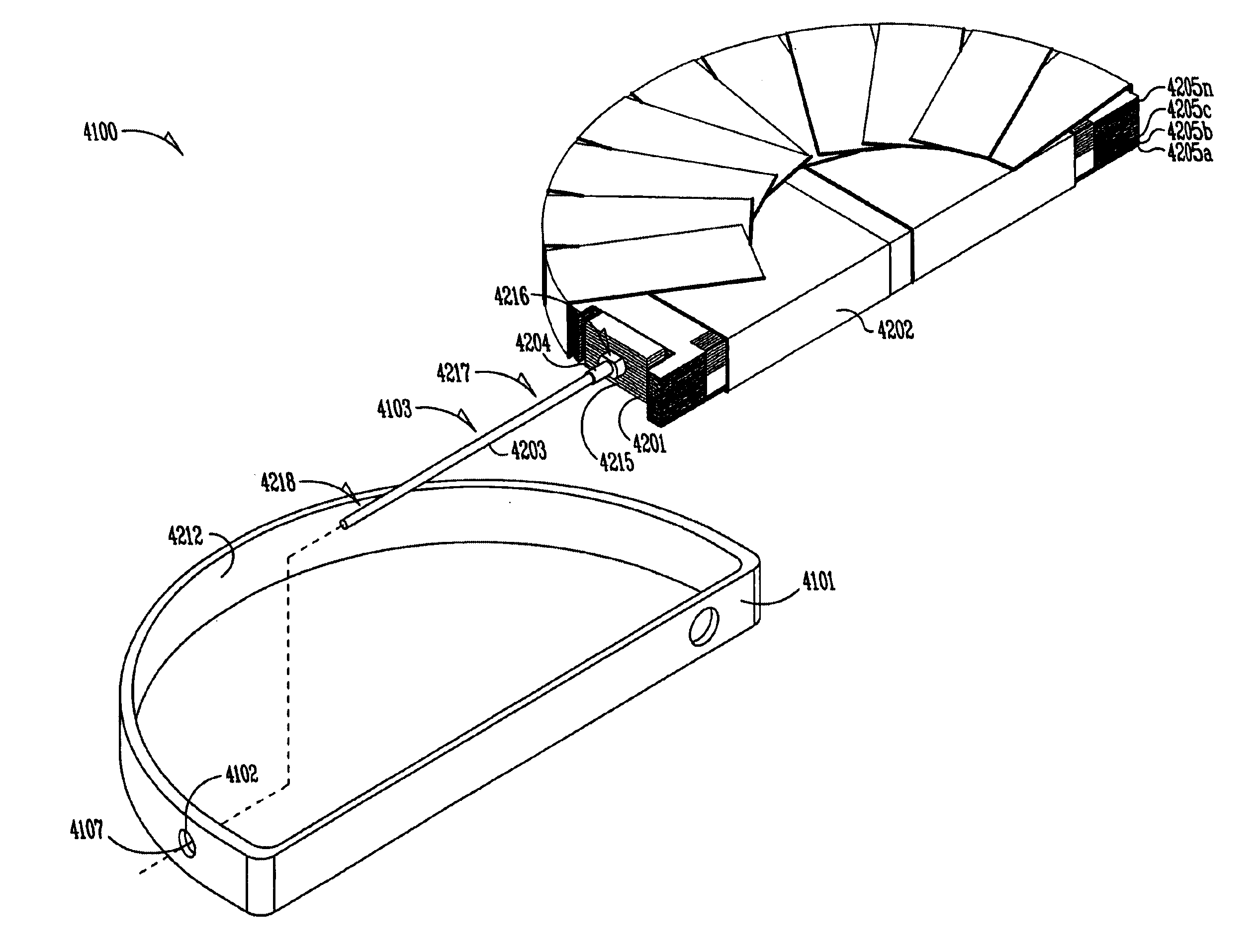
case 4101

includes a feedthrough hole 4107 which is drilled, molded, or punched in a portion of a wall of Feedthrough hole 4107 is in part defined by an edge 4107a which outlines the feedthrough hole within case 4101. Feedthrough hole 4107 provides a passage for connecting feedthrough assembly 4103 to circuitry outside of case 4101. In some embodiments, case 4101 includes two or more feedthrough holes for providing a second or third feedthrough assembly.

Feedthrough assembly 4103 and terminal 4104 connect capacitor elements to outside circuitry. In the exemplary embodiment, feedthrough assembly 4103 extends through feedthrough hole 4107 and is insulated from case 4101. Terminal 4104 is directly connected to case 4101. Alternatively, in some embodiments, the capacitor incorporates other connection methods, depending on other design factors. In various embodiments, two or more insulated feedthrough assemblies are employed.

In one embodiment, sealing member 4105, such as an epoxy, is deposited ar...


PUM

PropertyMeasurementUnit
Electrical conductivityaaaaaaaaaa
Shapeaaaaaaaaaa
Electrical conductoraaaaaaaaaa

Abstract

One embodiment includes a capacitor having a first anode stack having a first number of anode foils, a second anode stack having a second number of anode foils, where the first number of anode foils is different than the second number of anode foils. Another aspect provides a capacitor having a case having a curved interior surface, and first, second, and third capacitor modules that confront the curved interior surface of the case. One aspect provides a capacitor having one or more anodes and a cathode structure comprising a plurality of integrally connected cathode plates, the cathode structure having a serpentine shape, interweaving under and over each of the one or more anodes. One aspect provides a feedthrough assembly having an electrically conductive member dimensioned to extend at least partially through a feedthrough hole of a case of the capacitor, the conductive member having a passage therethrough. One aspect provides a capacitor having a first stack of capacitive elements a second stack of capacitive elements, wherein the first and second stacks are enclosed in separate compartments of a capacitor case that electrically isolate the electrolytes of each stack from one another. One aspect provides a capacitor case including a portion having opposing interior and exterior surfaces, with the portion having a hole; and a semi-permeable membrane adjacent the hole to regulate passage of fluids through the hole.

Description

FIELD OF THE INVENTIONThe present invention concerns capacitors, particularly flat aluminum electrolytic capacitors used in medical devices, such as implantable defibrillators, cardioverters, and pacemakers.BACKGROUNDSince the early 1980s, thousands of patients prone to irregular and sometimes life threatening heart rhythms have had miniature defibrillators and cardioverters implanted in their bodies, typically in the upper chest area above their hearts. These devices detect onset of abnormal heart rhythms and automatically apply corrective electrical therapy, specifically one or more bursts of electric current, to hearts. When the bursts of electric current are properly sized and timed, they restore normal heart function without human intervention, sparing patients considerable discomfort and often saving their lives.The defibrillator or cardioverter includes a set of electrical leads, which extend from a sealed housing into the walls of a heart after implantation. Within the housi...

Claims


Application Information

Patent Timeline
IPC IPC(8): H01G9/00H01G9/008
CPCH01G9/008A61N1/375H01G9/045A61N1/378H01G9/08H01G9/06H01G9/28H01G9/00H01G2009/0025Y10T29/417A61N1/3754A61N1/3782H01G9/02H01G9/035H01G9/055H01G9/07H01G9/10H01G9/145
Inventor O'PHELAN, MICHAEL J.SCHMIDT, BRIAN L.POPLETT, JAMES M.TONG, ROBERT R.KAVANAGH, RICHARD J.IYER, RAJESHBARR, ALEXANDER GORDONCHRISTENSON, LUKE J.WAYTASHEK, BRIAN V.SCHENK, BRIAN D.SHERWOOD, GREGORY J.
Owner CARDIAC PACEMAKERS INC
Why Eureka
Try Eureka