Receiving module and receiver

a receiver and module technology, applied in the direction of demodulation, electrical equipment, transmission noise suppression, etc., can solve the problems of insufficient isolation between the local oscillation signal terminal and the received signal terminal, the inability to simultaneously attenuate the local oscillation signal and the half-image signal with a single high frequency filter having a wide pass band, and the inability to have such steep characteristics

Inactive Publication Date: 2004-03-23
MURATA MFG CO LTD
View PDF11 Cites 27 Cited by
  • Summary
  • Abstract
  • Description
  • Claims
  • Application Information

AI Technical Summary

Problems solved by technology

When the single-end type mixer is used, isolation between the local oscillation signal terminal and the received signal terminal is not sufficient.
As a result, it is impossible to simultaneously attenuate both the local oscillation signal and the half-image signal with a single high frequency filter having a wide pass band.
However, it is impossible to have such steeper characteristics even by using surface acoustic wave filters and dielectric filters having good characteristics.
In addition, even if a high frequency filter having such steeper characteristics can be obtained, a select switch is necessary, with the result that the size of the receiver increases.

Method used


Image

  • Receiving module and receiver
  • Receiving module and receiver
  • Receiving module and receiver

Examples


first embodiment

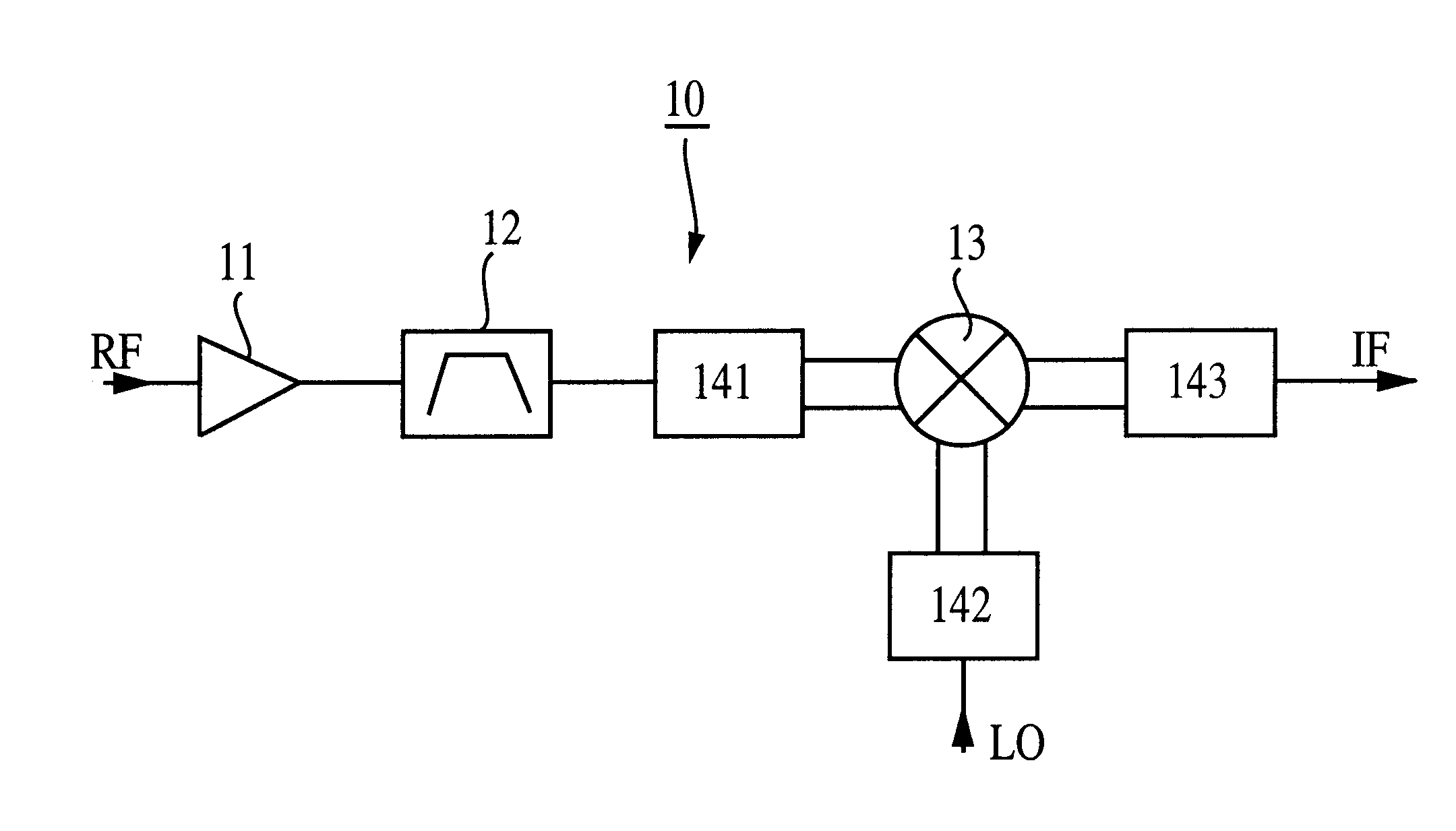
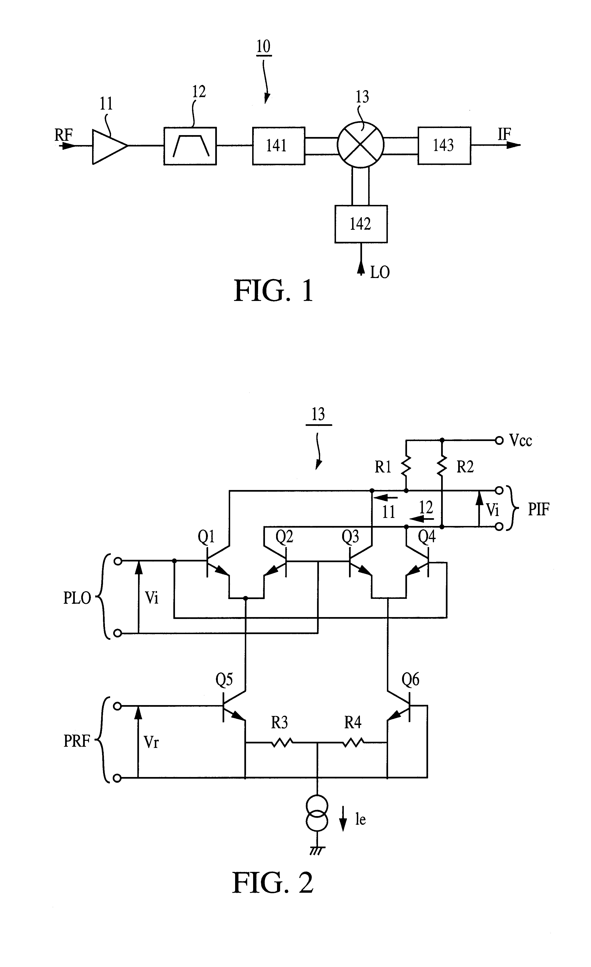
FIG. 1 is a block diagram of a receiving module according to the present invention. A receiving module 10 is constituted of a low-noise amplifier 11, a high frequency LC filter 12, a Gilbert-cell type mixer 13, and baluns 141 to 143.

A signal RF received by an antenna (not shown) is amplified by the low-noise amplifier 11. After passing through the LC filter 12 and the balun 141, the signal RF is input to the Gilbert-cell type mixer 13 to be mixed with a local oscillation signal LO input to the Gilbert-cell type mixer 13 via the balun 142. Then, an intermediate frequency signal IF obtained as the result of conversion by the Gilbert-cell type mixer 13 is output via the balun 143.

FIG. 2 is a circuit diagram of the Gilbert-cell type mixer 13 constituting the receiving module shown in FIG. 1. The Gilbert-cell type mixer 13 is constituted of six transistors Q1 to Q6 and four resistors R1 to R4.

The bases of the transistors Q1 and Q4, and the bases of the transistors Q2 and Q3 are connected...

second embodiment

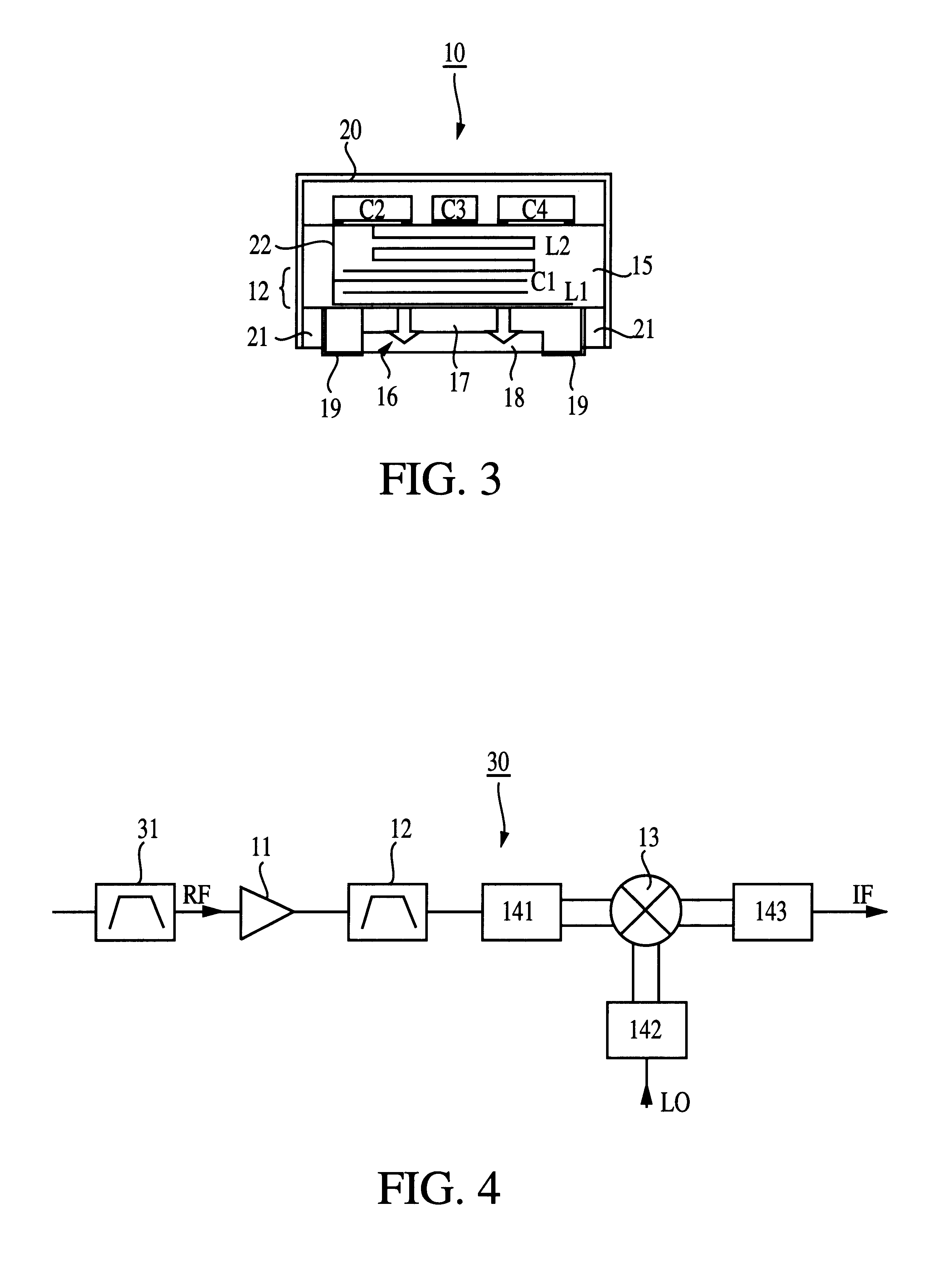
In the receiving module 30 of the second embodiment, since the Gilbert-cell type mixer is used, sufficient isolation between the terminals of the mixer can be obtained. As a result, leakage of received signals from a received signal terminal to a local oscillation signal terminal can be suppressed. Thus, since it is not necessary to dispose a high frequency filter for eliminating received signals between the local oscillation signal terminal and the local oscillation circuit, the receiving module can be made compact.

Since sufficient isolation can be obtained between the terminals of the mixer, and the Gilbert-cell type mixer capable of canceling even-order harmonics is used, leakage of received signals from a received signal terminal to a local oscillation signal terminal can be suppressed, and occurrence of half-image signals can also be suppressed. Therefore, the high frequency filter disposed between the low-noise amplifier and the mixer does not have to attenuate local oscillati...


PUM


Abstract

A receiving module and a TDMA-system receiver are adapted to broadening of bands of received signals and low frequencies of intermediate frequency signals. These apparatuses can be made compact and contribute to cost reduction. The receiving module is constituted of a low-noise amplifier, a high frequency LC filter, a Gilbert-cell type mixer, and baluns. A signal received by an antenna is amplified by the low-noise amplifier and is passed through the LC filter. After that, the signal is mixed with a local oscillation signal by the Gilbert-cell type mixer to be converted into an intermediate frequency signal.

Description

1. Field of the InventionThe present invention relates to receiving modules and receivers. More particularly, the invention relates to receiving modules and receivers using Gilbert-cell type mixers.2. Description of the Related ArtRecently, the Time Division Multiple Access (TDMA) wireless system has been adopted in the Japanese Personal Digital Cellular (PDC) system and in the European Global System for Mobile Communication (GSM). The Code Division Multiple Access (CDMA) wireless system has been adopted in the North American Interim Standard (IS)-95. The TDMA system and the CDMA system are rapidly spreading as wireless communication apparatuses and communication costs are becoming cheaper owing to the efforts of apparatus vendors. A receiver that can be incorporated in both the TDMA wireless system and the CDMA wireless system will be described below.FIG. 6 shows a block diagram of a conventional receiver. A signal RF received by an antenna 1 is amplified by a low-noise amplifier 2...

Claims


Application Information

Patent Timeline
Patent Type & Authority Patents(United States)
IPC IPC(8): H03D7/14H04B1/26
CPCH03D7/1425H03D7/1433H03D7/1458H03D2200/0023
Inventor TONEGAWA, KENYOSHIMOTO, YOSHIHIROSHIMADA, NORIHIROSASAKI, JUNBANDO, TOMOYA
Owner MURATA MFG CO LTD
Why Eureka
Try Eureka