

Continuous, laminar flow water-based particle condensation device and method
a technology of continuous flow and condensation device, applied in auxillary pretreatment, instruments, separation processes, etc., can solve the problems of low flow rate, low working fluid flow rate, toxic chemicals used as working fluids, and system failure to work well for suspended particles in air, etc., to achieve greater temperature difference and improve performan
Inactive Publication Date: 2004-03-30
AEROSOL DYNAMICS INC
View PDF20 Cites 69 Cited by
- Summary
- Abstract
- Description
- Claims
- Application Information
AI Technical Summary
Benefits of technology
This approach enables a continuous laminar flow with higher supersaturation ratios, effectively activating smaller particles for detection and analysis, improving the efficiency of particle growth and detection without the need for toxic chemicals.
Problems solved by technology
CPCs suffer from two general issues: low flow rates and the use of toxic chemicals as working fluids.
These systems do not work well for particles suspended in air when the condensing fluid is water.
Generally, the smaller the particle the more difficult it is to condense vapor on it, and for any device, there is a smallest particle size which can be activated for condensational growth.
Method used
View moreImage
Smart ImageViewing Examples

Examples
Embodiment Construction
has been presented for purposes of illustration and description. It is not intended to be exhaustive or to limit the invention to the precise form disclosed. Many modifications and variations are possible in light of the above teaching. The described embodiments were chosen in order to best explain the principles of the invention and its practical application to thereby enable others skilled in the art to best utilize the invention in various embodiments and with various modifications as are suited to the particular use contemplated. It is intended that the scope of the invention to be defined by the claims appended hereto.
Login to View More PUM
| Property | Measurement | Unit |
|---|---|---|
| temperature | aaaaa | aaaaa |
| temperature | aaaaa | aaaaa |
| temperature | aaaaa | aaaaa |
Abstract
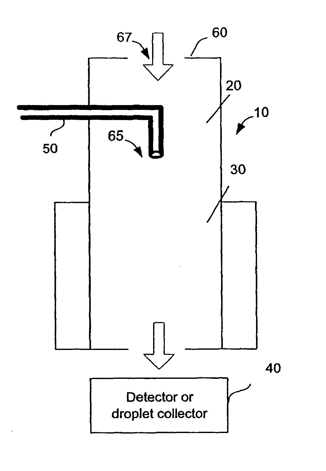
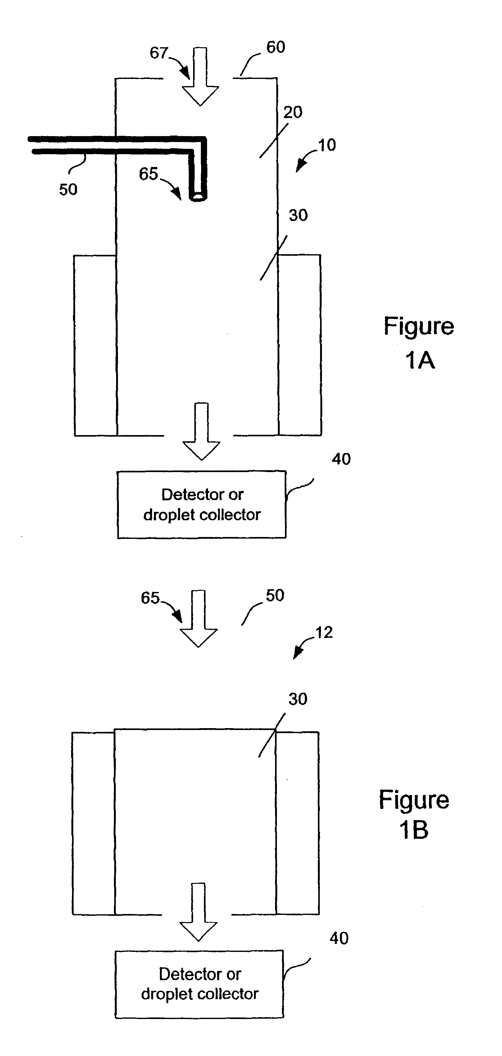
An apparatus and method for producing a diffusive, continuous laminar flow for particle growth via condensation of vapors with a mass diffusivity near or higher than the thermal diffusivity of the surrounding gas. In an exemplary embodiment, the method uses the condensation of water vapor onto particles suspended in air.
Description
1. Field of the InventionThe present invention is directed to the measurement of airborne particles and aerosols through condensational growth.2. Description of the Related ArtAirborne particles are ever present in the environment. Microscopic particles in the air include soil, smoke, photochemical, salt, dusts, fumes, mists, smog, and atmospheric water or ice particles. The presence of these particulates affects visibility, climate, health and quality of life. These airborne particles are examples of aerosols. Aerosols are generally defined as solid or liquid particles suspended in a gas.Many measurement methods for aerosol particles rely on condensational growth to enlarge particles to a size that can be detected by optical or other means. Condensational growth is also used to enable the collection of particles for chemical analysis. One type of particle measurement device is commonly referred to as a condensation particle counter (CPC). CPCs specifically examine the number concen...
Claims
Login to View More Application Information
Patent Timeline
 Patent Type & AuthorityPatents(United States)
IPC IPC(8): G01N15/06
CPCG01N15/065
InventorHERING, SUSANNE VERASTOLZENBURG, MARK RICHARD
OwnerAEROSOL DYNAMICS INC