Planar antenna for beam scanning

a scanning plane and beam technology, applied in the direction of individual energised antenna arrays, resonant antennas, particular array feeding systems, etc., can solve the problems of difficult to form a thin structure, difficult to reduce the size of the power feeding substrate 6, and large number of assembly steps, so as to achieve excellent thin structure and simplify the assembly process.

Inactive Publication Date: 2004-04-13
KOKUSA ELECTRIC CO LTD
View PDF7 Cites 21 Cited by
  • Summary
  • Abstract
  • Description
  • Claims
  • Application Information

AI Technical Summary

Benefits of technology

An object of the present invention is to provide a small beam scanning plane antenna which is excellent in terms of its thin structure and simplification of its assembly process.

Problems solved by technology

Thus, the number of assembly steps is large and it is difficult to form a thin structure because of its stereo structure.
On the other hand, if this distance is prolonged to avoid this phenomenon, the connecting line 16 is prolonged, so that reduction in the size of the power feeding substrate 6 becomes difficult to achieve and further, loss on the connecting line increases.

Method used


Image

  • Planar antenna for beam scanning
  • Planar antenna for beam scanning
  • Planar antenna for beam scanning

Examples


example

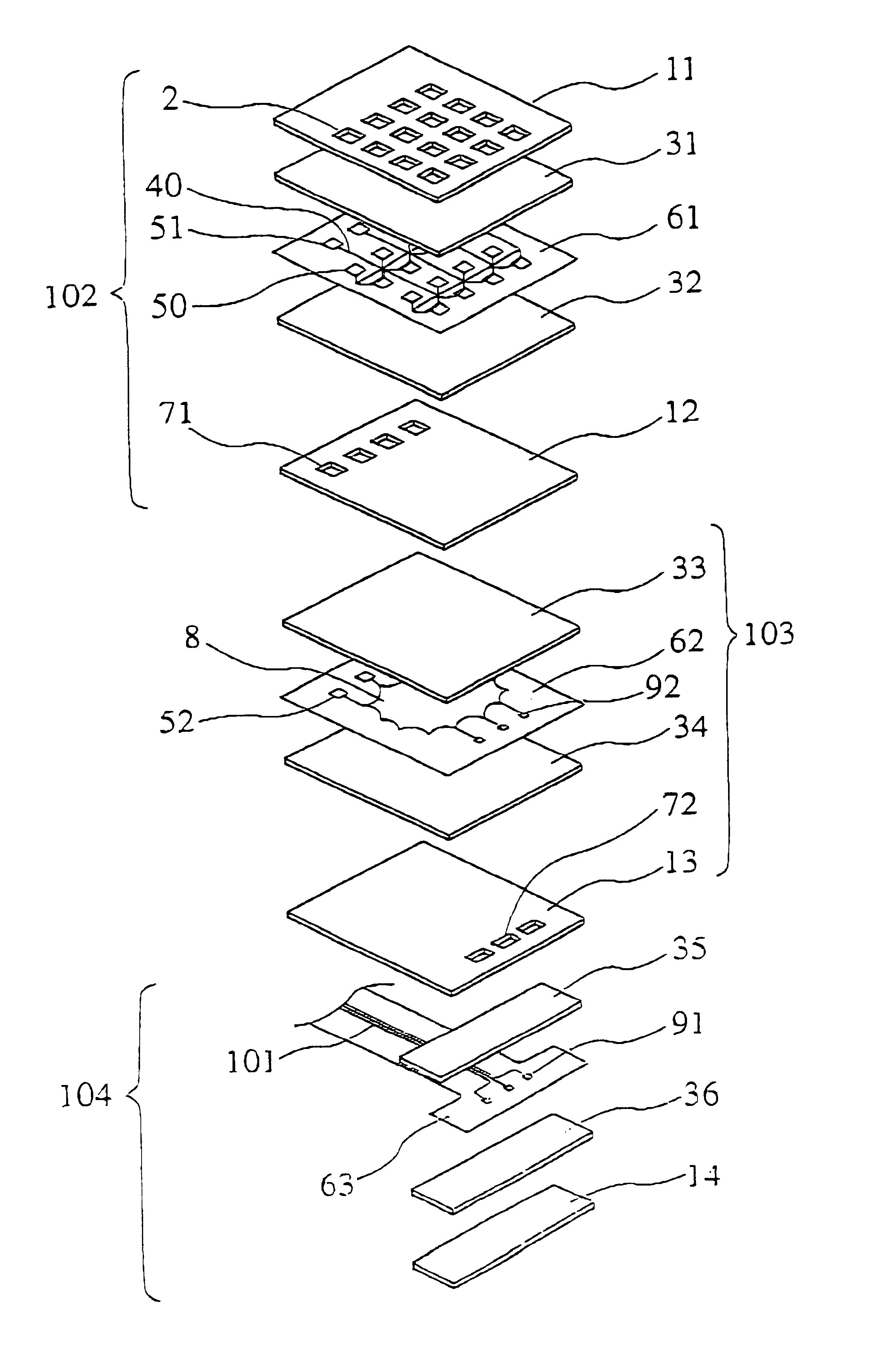
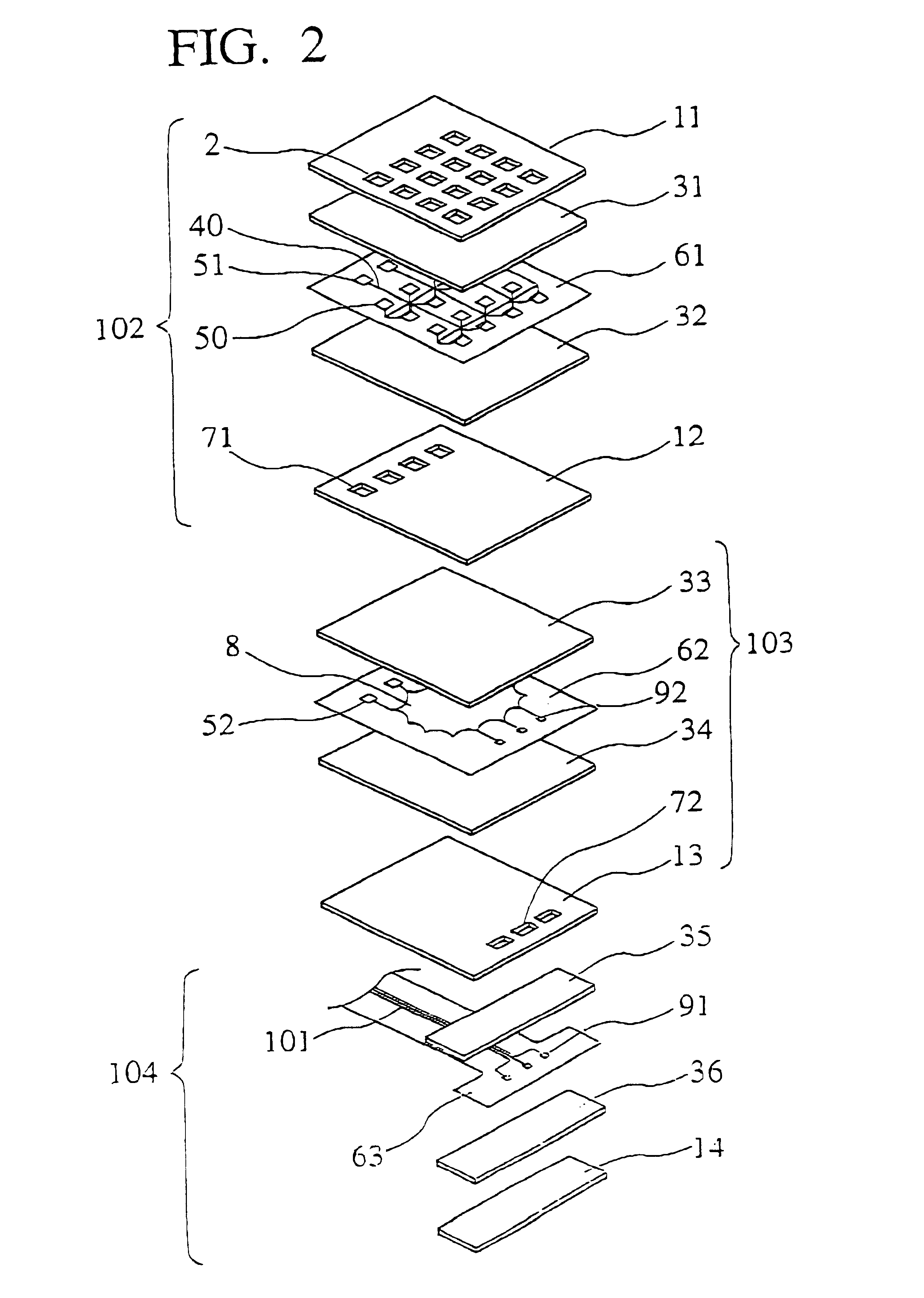
As shown in FIG. 2, the beam scanning plane antenna according to an embodiment of the present invention is formed by stacking a beam scan antenna portion 102, a Rotman lens portion 103 and a system connecting portion 104 in order from top.

As shown in FIG. 2, the beam scanning antenna portion 102 is formed by stacking the first grounding conductor 11, the first dielectric 31, the power feeding substrate 61, the second dielectric 32 and the second grounding conductor 12 in order from top.

A plurality of antenna groups are formed on the power feeding substrate 61 by removing unnecessary copper foil from copper coated lamination film in which copper foil having the thickness of 35 .mu.m is bonded on polyimide film having the thickness of 25 .mu.m as its foundation material. Each antenna group is constituted of an irradiating element 50, a power feeding line 40 connected thereto and a first connecting portion 51 connected electromagnetically to the Rotman lens portion 103.

As the first gro...


PUM


Abstract

A beam scanning plane antenna is formed by stacking, in order, a system connecting portion, a Rotman lens portion, and a beam scanning antenna portion. The system connecting portion is formed by stacking, in order, a fourth grounding conductor, a sixth dielectric, a connecting substrate and a fifth dielectric. The Rotman lens portion is formed by stacking, in order, a third grounding conductor, a fourth dielectric, a Rotman lens substrate and a third dielectric. The beam scanning antenna portion is formed by stacking, in order, a second grounding conductor, a second dielectric, a power feeding substrate, a first dielectric and a first grounding conductor. A plurality of antenna groups that each include an irradiating element, a power feeding line and a first connecting portion, are formed on the power feeding substrate. The Rotman lens substrate includes a Rotman lens pattern, a second connecting portion and a third connecting portion.

Description

The present invention relates to a beam scanning plane antenna used for performing transmission / reception in micro wave band or millimetric wave band.The beam scanning antenna, which irradiates with electric waves in all directions of a specific range by changing the angle of the irradiation direction with time passage, often uses Rotman lens as a lens for converting signals from its system to scanning electric waves. As shown in FIG. 1A, this Rotman lens has a micro strip structure comprising a power feeding substrate 6 on which connecting lines 10 for connecting with the system, and power feeding lines 4 are formed; and a grounding conductor 3 attached on the rear face thereof. The power feeding lines 4 are connected to irradiating elements 5 through coaxial lines 15 connected to connectors.To reduce the quantity of components or the size thereof, as shown in FIG. 1B, it is permissible to have a construction which connects the power feeding lines 4 with the irradiating elements 5 ...

Claims


Application Information

Patent Timeline
Patent Type & Authority Patents(United States)
IPC IPC(8): H01Q13/10H01Q21/00H01Q15/08H01Q3/44H01Q21/06H01Q15/00H01Q25/00H01Q3/00
CPCH01Q3/44H01Q13/10H01Q15/08H01Q21/0031H01Q21/0087H01Q21/064H01Q25/008H01Q13/00
Inventor MICHISAKA, TAKAOOHTA, MASAHIKOMIZUGAKI, HISAYOSHIKANAMARU, KIICHI
Owner KOKUSA ELECTRIC CO LTD
Why Eureka
Try Eureka