Drying plant and method for drying wood

a drying plant and wood technology, applied in drying, light and heating equipment, furnace types, etc., can solve the problems of environmental pollution risk, complicated situation, and inevitable appearance of accompanying problems

Inactive Publication Date: 2004-04-27
SKROTSKY VIKTOR GEORGIEVICH +1
View PDF19 Cites 16 Cited by
  • Summary
  • Abstract
  • Description
  • Claims
  • Application Information

AI Technical Summary

Problems solved by technology

While using those systems, accompanying problems inevitably appear due to the following facts.
The situation becomes much more complicated when an incomplete fuel combustion takes place, because in this case the combustion products are fouled not only with soot (i.e., unburned carbon particles), but also with dry distillation products as well, consisting of CO and a number of hydrocarbons, which are usually chemically active, smell specifically, have relatively low temperatures of boiling, etc.
Furthermore, there is a risk of environmental pollution due to a possible formation of dioxins and furans as a result of condensation reactions, when gaseous products of wood burning are cooled with the presence of even minimal amounts of chlorine (although furnace ashes do not contain these products).
As a result, to ensure ecological safety of the drying plants and to produce high-quality dry wood materials, considerable expenses are required to purify combustion products and drying agents.
Besides, special devices are required to provide necessary drying conditions (e.g., different humidifiers or steam generators are used to maintain the necessary level of humidity), resulting in a sophisticated design, higher prices and complicated maintenance.
Nevertheless, neither the measures taken nor considerable expenses can guarantee either necessary ecological safety or high quality of dried materials.

Method used


Image

  • Drying plant and method for drying wood
  • Drying plant and method for drying wood
  • Drying plant and method for drying wood

Examples


Embodiment Construction

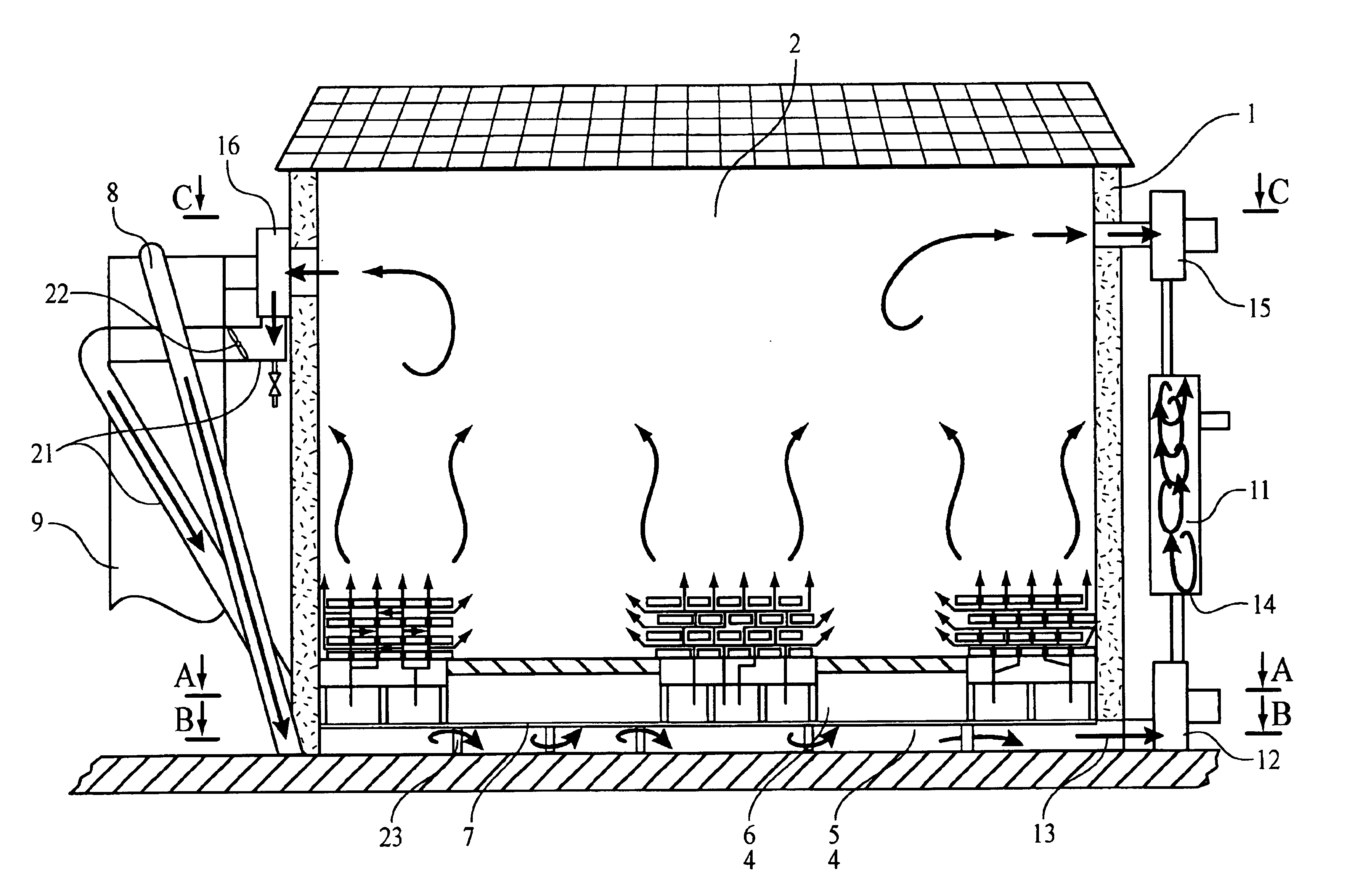
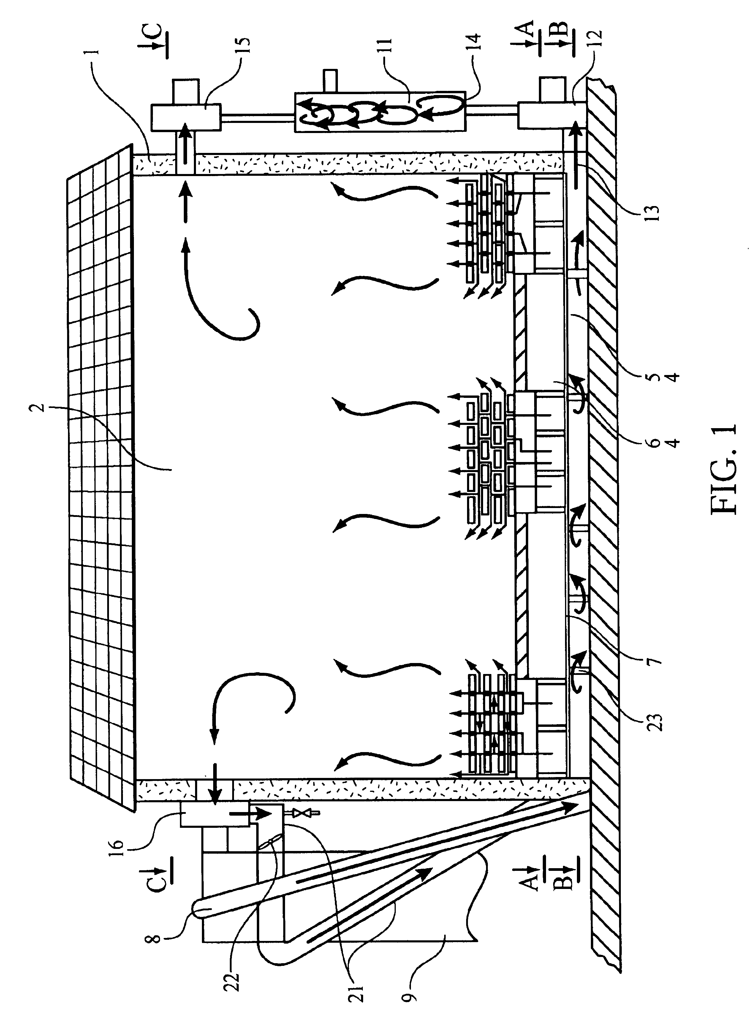
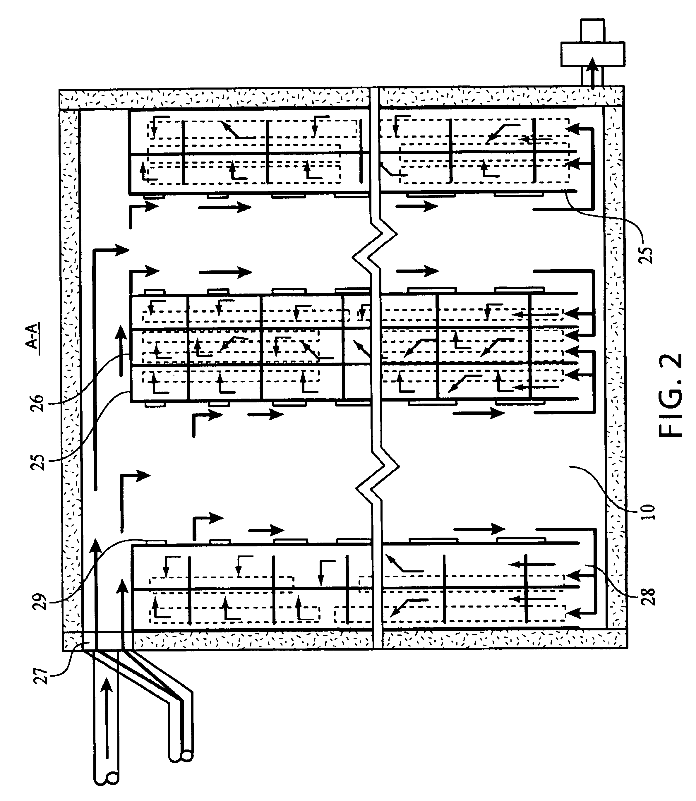
The drying plant consists of the heat-insulated drying chamber (1) with the free internal space (2), the furnace (3) located close to the drying chamber (1), the bottom of the drying chamber (4) that is designed with two cavities (5 and 6), horizontally arranged and separated from each other by the hermetic partition (7) made of diathermic material. The lower cavity (5) in the bottom (4) of the drying chamber (1) is designed in such a way as to provide forced feeding of furnace gases into the cavity (5) from the exhaust pipe (8) of the furnace flue (9). The upper cavity (6) in the bottom (4) of the drying chamber (1) is designed in such a way as to provide feeding of the air (drying agent) heated in the furnace flue (9) into said cavity (6); in the upper cavity (6), the heated air is distributed among the air distribution channels (10) to interact with the material to be dried located in the free internal space of the drying chamber (1). There is a possibility to provide forced feed...


PUM


Abstract

The invention relates to drying equipment and can be used in wood and wood treatment industries, etc., whenever parameters and procedures necessary to dry materials such as wood are used. The invention allows the drying process to achieve a higher degree of environmental protection, a larger product output and power saving features on the account of the following design of the plant: the drying chamber (1) which contains the material to be dried includes a bottom (4) which has two cavities (5,6); hot combustion products are injected into one of these cavities (5) from the flue pipe (9) of the furnace (3) which is used to burn wood waste; hot air is supplied into the other cavity (6), whereby said air is heated in pipes which are located in the flue (9), and is used as a drying agent. The hot drying agent is supplied from the cavity (6) in the bottom and circulates through air distribution channels in the lower part of the drying chamber (1) where it passes through the material to be dried and rises in the top portion of the internal open space of the drying chamber (1). From that point, one part of the drying agent is fed into a closed circuit in the flue (9) of the furnace and is heated therein, and the other part of said drying agent is directed into a condensate cleaning unit (11) where it is mixed with furnace gases and purifies these gases by condensation.

Description

Applicants claim priority under 35 U.S.C. .sctn.119 of Russian Application No. 99122270, filed Oct. 27, 1999. Applicants also claim priority under 35 U.S.C. .sctn.365 of PCT / RU00 / 00419 filed Oct. 24, 2000. The international application under PCT article 21 (2) was not published in English.The invention relates to drying equipment and can be used in timber industry, woodworking and other branches of industry, whenever parameters and procedures necessary to dry materials as wood are used.Prior ArtDrying plants are known from prior art that include a batch-operating drying chamber and a furnace located near it, in which woodworking waste products may be and are primarily used as fuel to generate heat necessary for drying. Usually, the furnace gases or a mixture of furnace gases with air are used in such systems (e.g., see, Spravochnik po sushke drevesiny (Wood-drying reference book) edited by E. S. Bogdanov, Moscow, Lesnaya promyshlennost, 1990, pp. 38-63, patent RU 2105941, and the fo...

Claims


Application Information

Patent Timeline
Patent Type & Authority Patents(United States)
IPC IPC(8): F26B23/02F26B9/06F26B25/00F26B21/06F26B23/00F26B21/00F26B3/04
CPCF26B9/06F26B21/002F26B21/06F26B23/028F26B25/005F26B25/006F26B2210/16
Inventor SKROTSKY, VIKTOR GEORGIEVICHSKROTSKAYA, OLGA PANTELEIMONOVNA
Owner SKROTSKY VIKTOR GEORGIEVICH
Why Eureka
Try Eureka