Radial pump

a radial pump and cylinder head technology, applied in the direction of wind motors with parallel air flow, non-positive displacement fluid engines, liquid fuel engine components, etc., can solve the problems of small discharge angle and reduced flow volum

Inactive Publication Date: 2004-06-29
TCG UNITECH AKTIENGES
View PDF10 Cites 10 Cited by
  • Summary
  • Abstract
  • Description
  • Claims
  • Application Information

AI Technical Summary

Benefits of technology

to avoid the above disadvantages and to improve the efficiency of a radial-flow pump.
Preferably it is provided that the impeller vanes be configured as flexible elements made of elastic material, preferably sheet steel. At low speeds the pressures exerted on the impeller vanes are low; the delivered flow volume is the same as in the case of rigid vanes. At high speeds, however, the Coriolis forces of the coolant flow will cause a deformation of the blades resulting in smaller discharge angles and thus a reduced flow volume. This is due to the fact that a deformation of the vanes effected by the Coriolis forces will cause the discharge angles defined between the impeller vanes and the impeller tangential planes to decrease with increasing speed. Compared with rigid impeller vanes the flexible vanes are flatter and thinner. The efficiency of flexible vanes is significantly higher than that of rigid vanes, while throttle losses will be avoided.
Maximum deformation of the impeller vanes is limited by the use of supporting vanes, i.e., preferably at least in the direction of decreasing discharge angles, the impeller vanes being preferably provided with one supporting vane each. In addition to, or instead of the supporting vanes it may be provided that the impeller vanes be connected to each other by a synchronizing ring. This ring will effect constant parallel alignment of the impeller vanes and prevent bending or displacement of individual vanes. The synchronizing ring further prevents undue excitation of vibrations of individual impeller vanes. If the synchronizing ring is employed together with the supporting vanes, it should preferably be positioned outside of the supporting vanes in radial direction.
To permit external control of the flow volume handled by the radial-flow pump, it will be a special advantage if the temperature-sensitive element can be heated by means of a heating device.

Problems solved by technology

At high speeds, however, the Coriolis forces of the coolant flow will cause a deformation of the blades resulting in smaller discharge angles and thus a reduced flow volume.

Method used


Image

  • Radial pump
  • Radial pump
  • Radial pump

Examples


Embodiment Construction

with reference to the enclosed drawings.

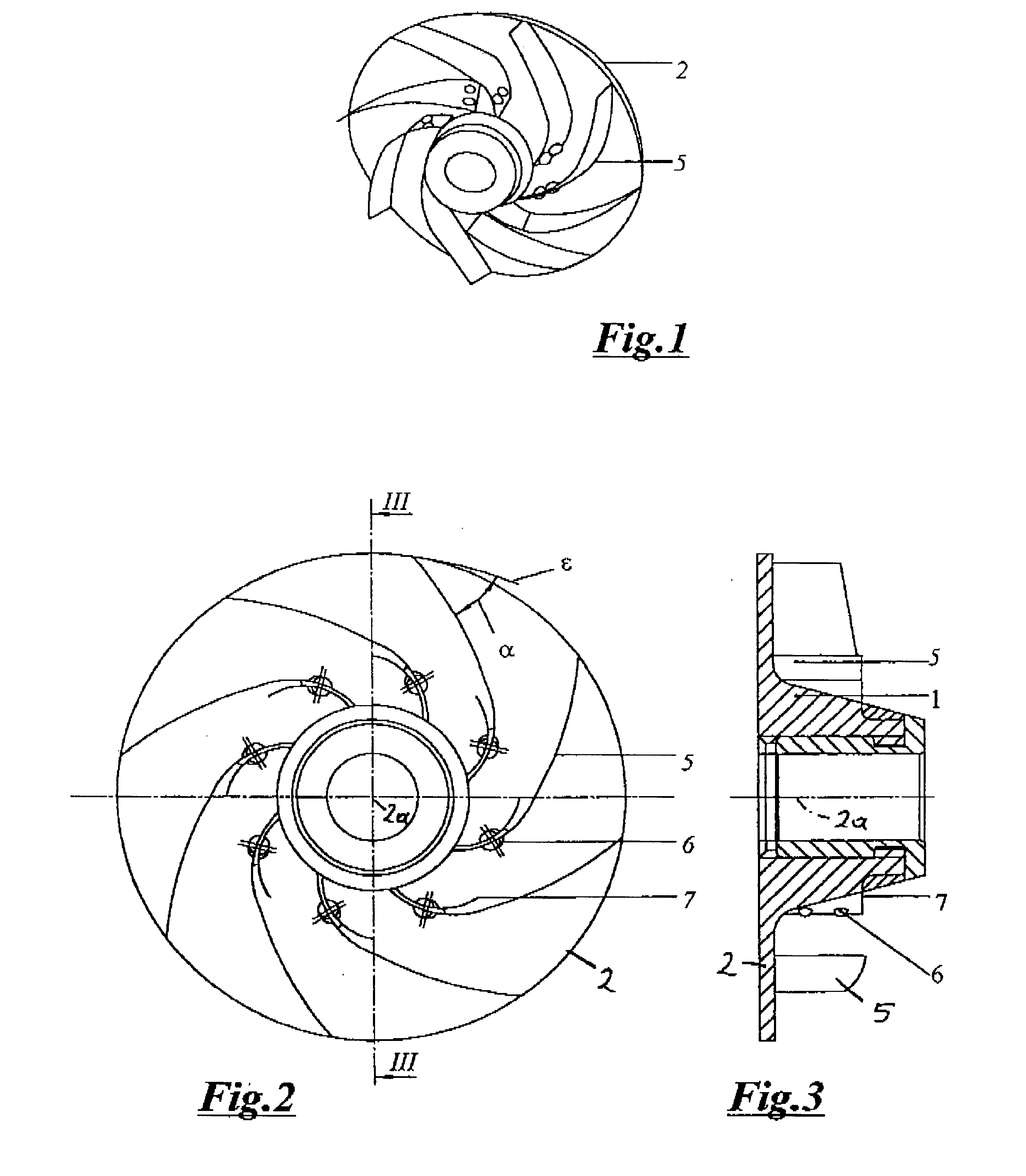
FIG. 1 shows an impeller of a radial-flow pump according to the invention, in a first variant, in an oblique view,

FIG. 2 is a view of the impeller from above,

FIG. 3 shows the impeller in a section along line III--III in FIG. 2,

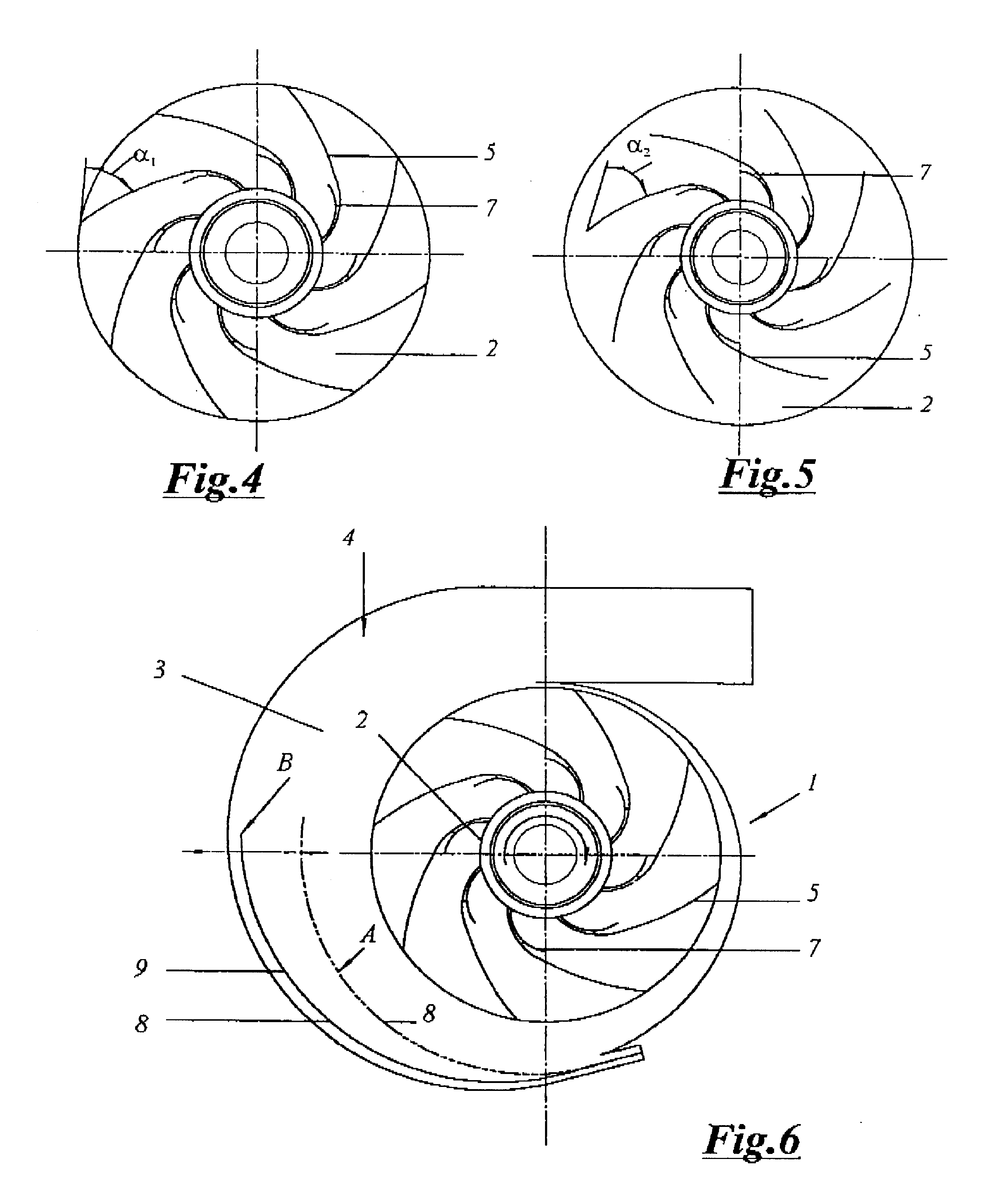
FIG. 4 shows the impeller with the impeller vanes being in a first position,

FIG. 5 shows the impeller with the impeller vanes being in a second position,

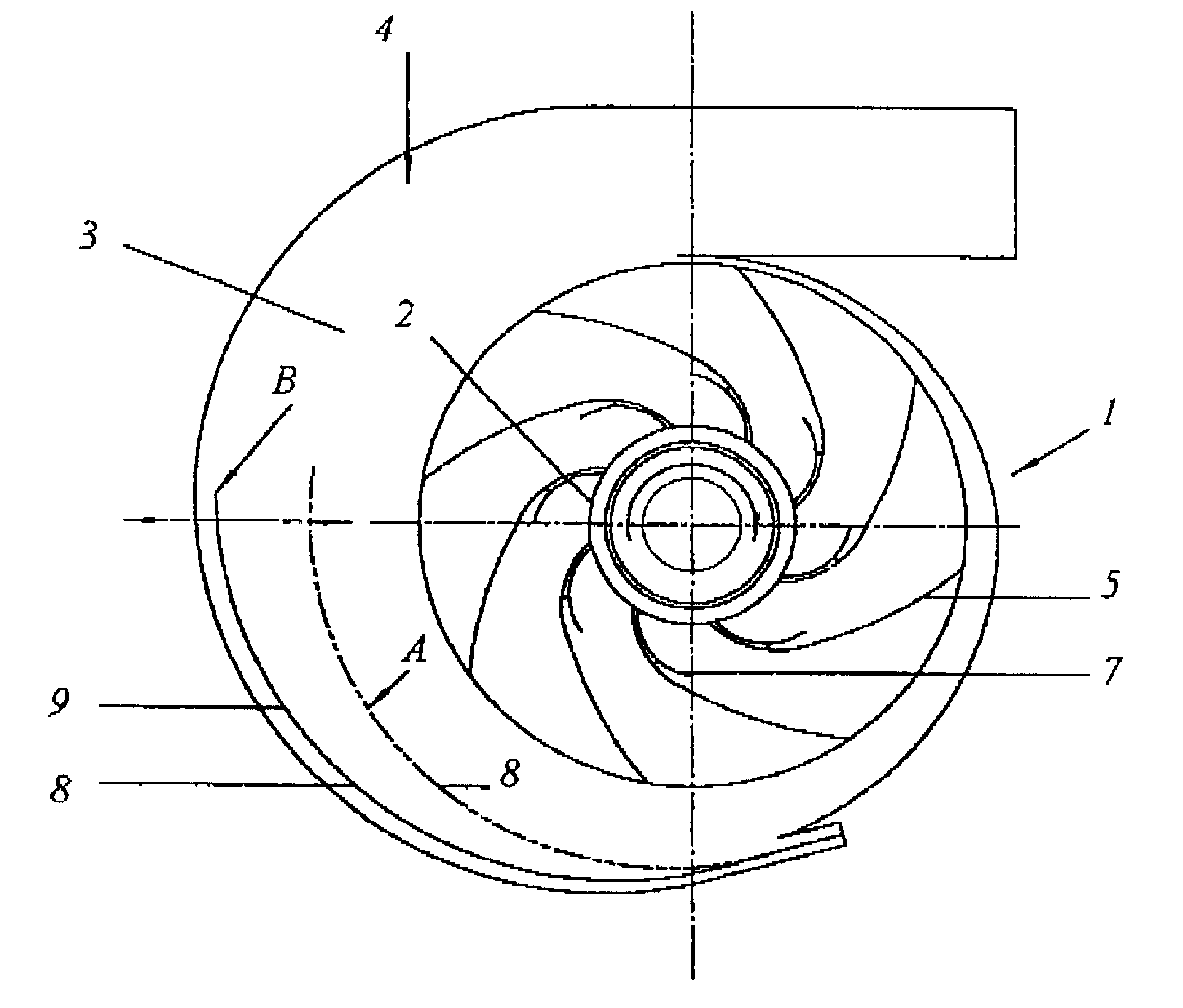
FIG. 6 shows the radial-flow pump with the directing device,

FIG. 7 shows an impeller of a radial-flow pump according to the invention, in a second variant, in a view from above,

FIG. 8 is an oblique view of this impeller,

FIG. 9 shows an impeller of a radial-flow pump according to the invention, in a third variant,

FIG. 10 is a characteristic diagram of the radial-flow pump.

Parts of identical function bear identical reference numerals in all figures.

The radial-flow pump 1 is provided with an impeller 2 and a directing device 4 constituted by a spiral casing 3. The impeller ...


PUM


Abstract

A radial-flow pump (1), and especially a coolant pump for an internal combustion engine, comprising an impeller (2) provided with vanes (5) and a directing device (4) including at least one temperature- and / or speed-sensitive element for temperature-dependent control of the coolant flow, where at least one impeller vane (5) and / or the directing device (4) is configured as a speed-sensitive element. In order to increase efficiency, the proposal is put forward that the impeller vanes (5) should be elastically deformable by Coriolis forces of the coolant flow, the discharge angles (alpha), which are preferably defined between impeller vanes (5) and impeller tangential planes (epsilon), decreasing with an increase in speed.

Description

This invention relates to a radial-flow pump, and especially a coolant pump for an internal combustion engine, comprising an impeller provided with vanes and a directing device including at least one temperature- and / or speed-sensitive element for temperature-dependent control of the coolant flow, at least one impeller vane and / or the directing device being configured as a speed-sensitive element.Coolant pumps for use with engines of large passenger cars are often required to handle considerable flow volumes even at low engine speeds. As a consequence extremely large volumes are delivered at maximum speed, which in turn will lead to unduly high pressures in the coolant circulation system. Short circuits to reduce the coolant volume passing through the engine cooling system must have large cross-sections and will inevitably result in power losses.DESCRIPTION OF THE PRIOR ARTPublication DE 37 09 231 A1 describes an impeller made of an extendible elastic material, which is configured s...

Claims


Application Information

Patent Timeline
Patent Type & Authority Patents(United States)
IPC IPC(8): F04D15/00
CPCF04D15/0027F04D15/0038Y10S416/50F04D29/247
Inventor PREINFALK, MARKUSKLAUS, HEINZATSCHREITER, FRITZ
Owner TCG UNITECH AKTIENGES
Why Eureka
Try Eureka