Crack detection in fracture-critical machine parts

a technology of crack detection and machine parts, applied in the field of crack detection in fracture-critical machine parts, can solve the problems of unrealistic containment of this type of failure, disassembly, inspection and reassembly over the life of the engine, etc., and achieve the effects of low failure rate, high reliability, and extremely high temperature in the sensor and environmen

Inactive Publication Date: 2004-06-29
RAYTHEON TECH CORP
View PDF7 Cites 56 Cited by
  • Summary
  • Abstract
  • Description
  • Claims
  • Application Information

AI Technical Summary

Benefits of technology

Objects of the invention include crack detection on machinery, including particularly rotating components: which does not require memory and long-term history; in which the diagnostic signals do not gradually degrade with time; substantially anywhere in the rotating structure; which is essentially instantaneous; in which the degree of crack progression is sensed quantumly; wherein cracks may be detected in rotating parts in which both vibratory and centrifugal forces are extremely large; wherein temperatures in the sensor and environment are extremely high; which is readily implemented using processes and materials known to have satisfactory historical usage, with low failure rates and high reliability.
The invention permits sensing the development of cracks in and near the surface of rotating and other parts, which cracks may be located remotely from the sensor itself, and even in hidden areas (such as on a back surface of the part). By causing the loss of one wire commensurately with each incremental length of a crack, the invention provides a quantum change in the impedance of the circuit, which is easy to process and present substantially instantaneous indications thereof.

Problems solved by technology

For example, in gas turbine engines, fan, compressor and turbine disks are fracture-critical.
Providing containment for this type of failure is unrealistic and it is not a standard practice.
The cost for disassembly, inspection and reassembly over the life of an engine is on the order of the initial cost of the engine.
Changes in electrical properties of the device are correlated with cracks in the disk.
However, this technology by its very nature is hard to apply in a rotational environment such as engine disks.
The diagnostic signals of the prior art gradually degrade with time, can be analyzed only using long-term histories; can only detect cracks that actually move past the sensor; and cannot detect cracks which are remote from the sensor or hidden on the rotating part.

Method used


Image

  • Crack detection in fracture-critical machine parts
  • Crack detection in fracture-critical machine parts
  • Crack detection in fracture-critical machine parts

Examples


Embodiment Construction

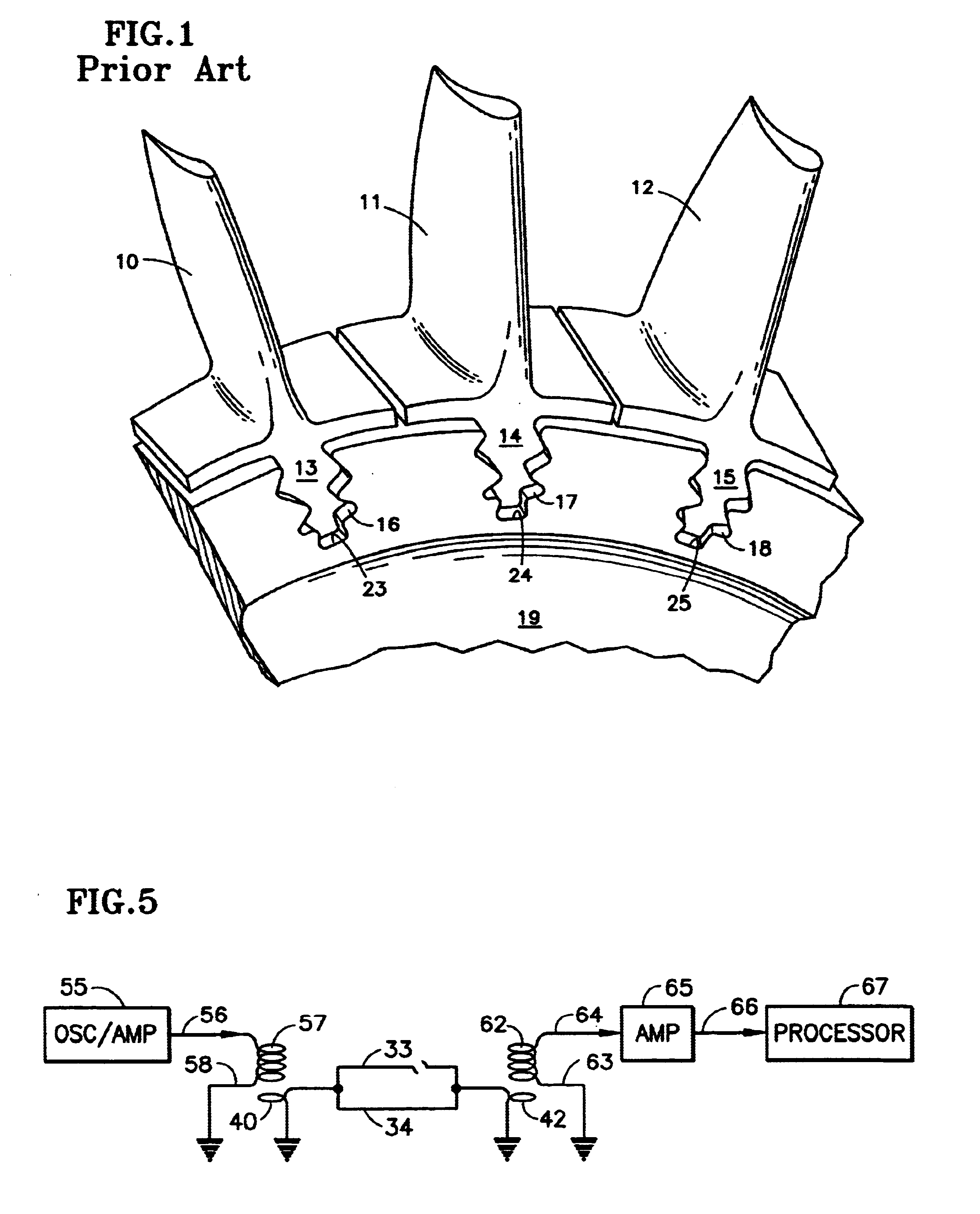
Referring to FIG. 1, the blades 10-12 of a gas turbine engine each have roots 13-15 which are captured by corresponding blade root sockets 16-18 in the turbine disk 19. Potential failure of an engine disk is typically preceded by cracks on and near the surface at the base 23-25 of the blade root sockets 16-18.

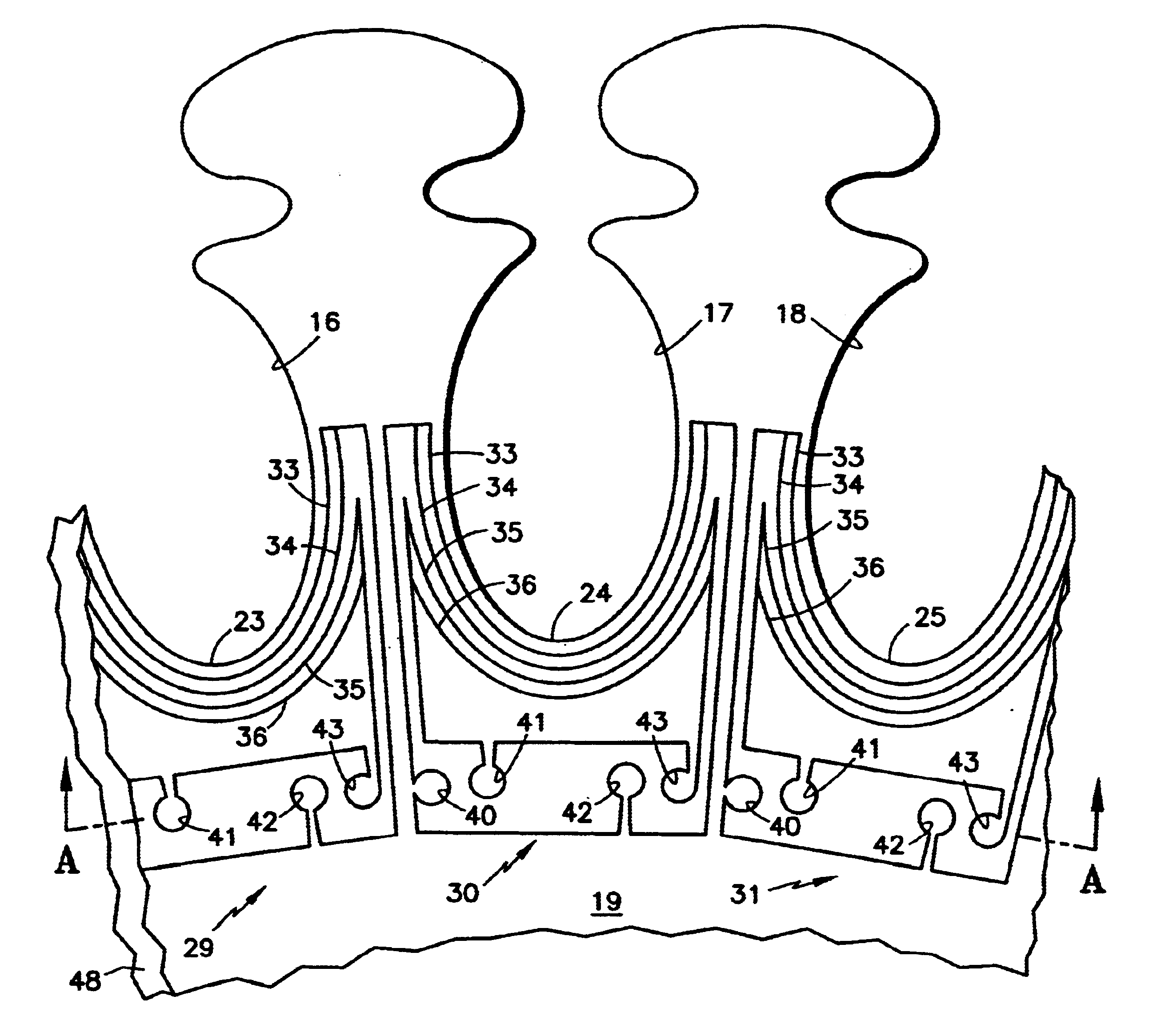
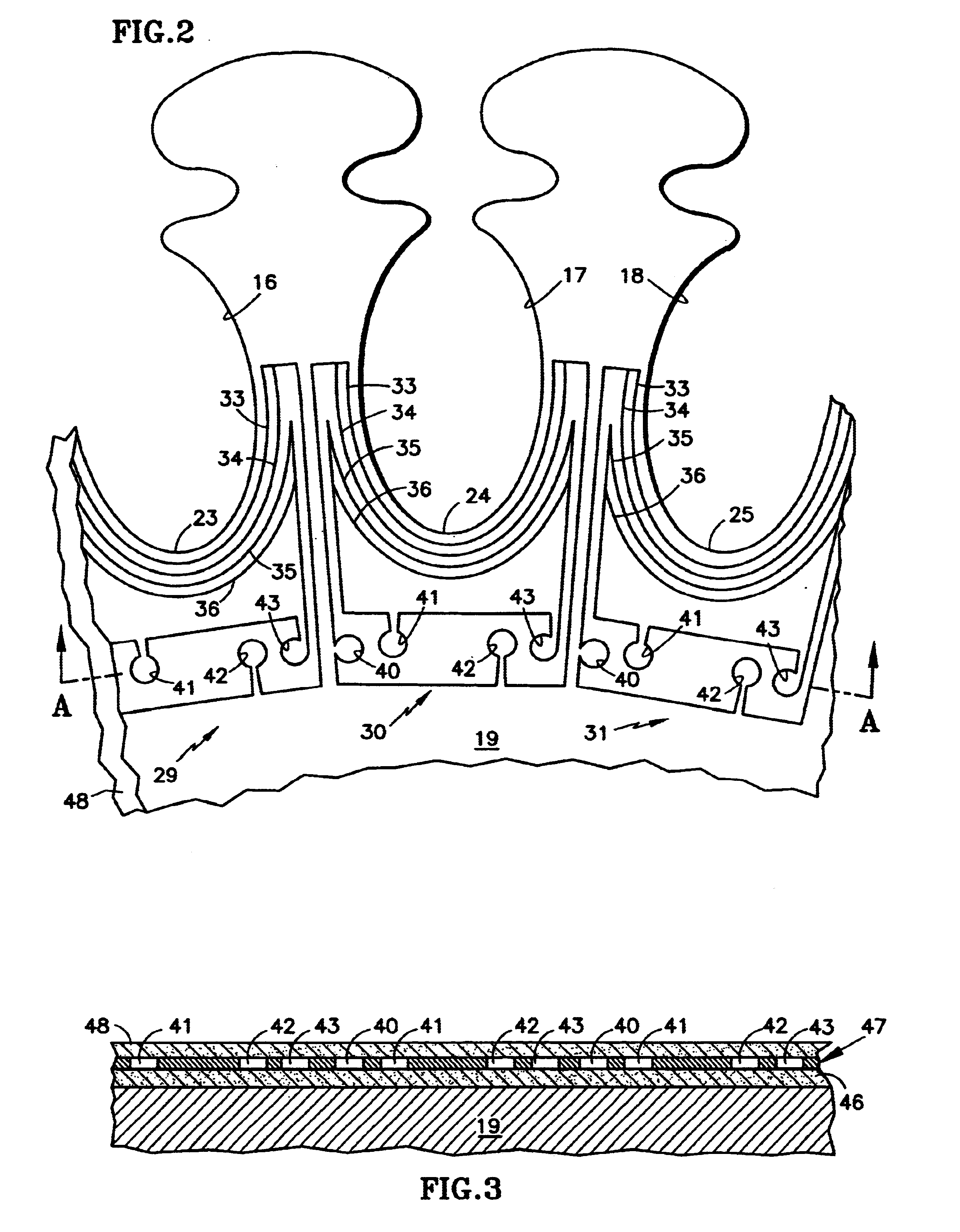
In FIG. 2, near the bas 23-25 of each blade root socket 16-18, a pair of circuits 29-31 each comprise a pair of wires 33, 34; 35, 36. Each pair is connected to corresponding excitation nodes 40, 41 and corresponding detection nodes 42, 43. In this embodiment, the excitation and detection nodes are inductive, and are represented in FIG. 2 as single turns of wire. In FIG. 3, assuming that the disk 19 is formed of titanium alloy, it may be first given an insulative coating 46, such as alumina on top of which there is deposited a layer 47 of titanium alloy, which after etching will form the circuitry, including the wires 33-36, the excitation and detection nodes 43, and the connect...


PUM

PropertyMeasurementUnit
electricalaaaaaaaaaa
magnetic couplingaaaaaaaaaa
radiusaaaaaaaaaa

Abstract

A plurality of wires (33, 34; 35, 36) are disposed near the bottom (23-25) of blade root sockets (16-18) of a rotating disk 39 of a gas turbine engine by vapor deposition and etching, the wires including connections to excitation nodes (40, 42) and detection nodes (41, 43). A nearby stationary member of the engine mounts an oscillator amplifier (55) which drives a coil (57) that excites the circuitry, and a coil (62) drives an amplifier (65) and a processor (67) which provides an indication of whether or not one or more of the wires are broken by a crack.

Description

This invention relates to sensing the impedance of conductors disposed to span expected cracks in and near the surface of fracture-critical machinery components.In gas turbine jet engines, and other rotating machinery, the designation "fracture-critical" is given to those components with enough energy, due to high rotational speeds and mass, to promote catastrophic failure. For example, in gas turbine engines, fan, compressor and turbine disks are fracture-critical. Providing containment for this type of failure is unrealistic and it is not a standard practice. Instead, fractures in the rotating components of gas turbine engines are avoided through adequate design and quality control margins, and through periodic inspections. The cost for disassembly, inspection and reassembly over the life of an engine is on the order of the initial cost of the engine.An alternative approach to managing failures in rotating parts is use of a sensor capable of detecting impending failure with suffic...

Claims


Application Information

Patent Timeline
Patent Type & Authority Patents(United States)
IPC IPC(8): C23C4/12F01D21/00F01D21/04G01N27/20
CPCC23C4/12F01D21/003F01D21/045G01N27/20G01N27/205
Inventor GASS, FRANK D.REY, GONZALO J.
Owner RAYTHEON TECH CORP
Why Eureka
Try Eureka