Vehicle air conditioner

a technology for air conditioners and passenger compartments, applied in the direction of vehicle cleaning, vessel parts, vessel construction, etc., can solve the problems of difficult to obtain a comfortable air-conditioning state in an entire passenger compartment, difficult to provide a uniform air temperature distribution or a uniform wind speed distribution in the passenger compartmen

Inactive Publication Date: 2004-07-06
DENSO CORP
View PDF4 Cites 2 Cited by
  • Summary
  • Abstract
  • Description
  • Claims
  • Application Information

AI Technical Summary

Benefits of technology

It is a second object of the present invention to provide a vehicle air conditioner capable of providing a uniform air temperature distribution or a uniform wind speed distribution in an entire passenger compartment by effectively using a direct air outlet from which conditioned air is directly blown to a passenger of the passenger compartment and an indirect air outlet from which conditioned air is indirectly blown to the passenger of the passenger compartment.
In addition, the air amount control unit increases the air amount blown from the indirect air outlet to be larger than the air amount blown from the direct air outlet, when the cooling state determining means determines that the proceeding state is in a later stage with respect to the predetermined stage. Further, when the cooling state determining means determines that the rapid cooling operation is ended, the air amount control unit reduces a total air amount blown into the passenger compartment to be smaller than that in the initial stage of the rapid cooling operation while supplying conditioned air from the indirect air outlet into the passenger compartment. Therefore, air conditioning feeling given to the passenger can be improved without a manual change of an air blowing control plate such as grills, an air outlet mode or an air blowing amount.
For example, the indirect air outlet is a wall-surface air blowing means for indirectly blowing conditioned air toward a passenger in the passenger compartment from an inner design wall portion of the passenger compartment, and the direct air outlet includes a seat air blowing means for directly blowing conditioned air toward a passenger on a seat in the passenger compartment. The cooling state determining means includes a rapid-cooling determining means for determining whether the rapid cooling operation is performed. Further, the air amount control unit includes a rapid-cooling amount control means for determining a first air amount to be blown from both of the wall-surface air blowing means and the seat air blowing means when the rapid-cooling determining means determines that the rapid cooling operation is performed, and a stationary-cooling amount control means for determining a second air amount to be blown from both of the wall-surface air blowing means and the seat air blowing means when the rapid-cooling determining means determines that the rapid cooling operation is not performed. Therefore, a uniform air temperature distribution or a uniform wind speed distribution in an entire passenger compartment can be provided by effectively controlling the air amount blown from the direct air outlet and the air amount blown from the indirect air outlet.

Problems solved by technology

Therefore, it is difficult to provide a uniform air temperature distribution or a uniform wind speed distribution in the passenger compartment.
As a result, it is difficult to obtain a comfortable air-conditioning state in an entire passenger compartment.

Method used


Image

  • Vehicle air conditioner
  • Vehicle air conditioner
  • Vehicle air conditioner

Examples


first embodiment

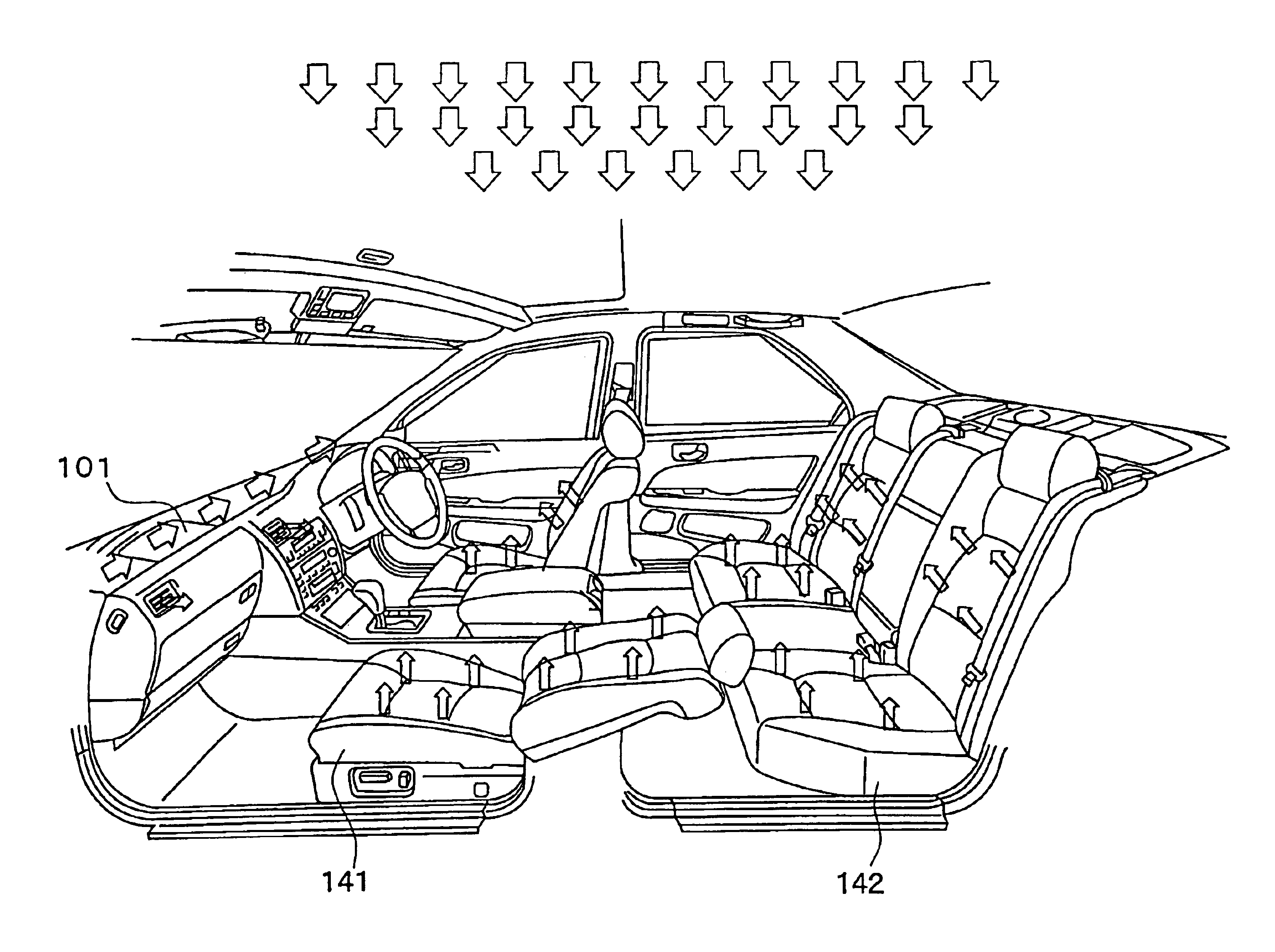
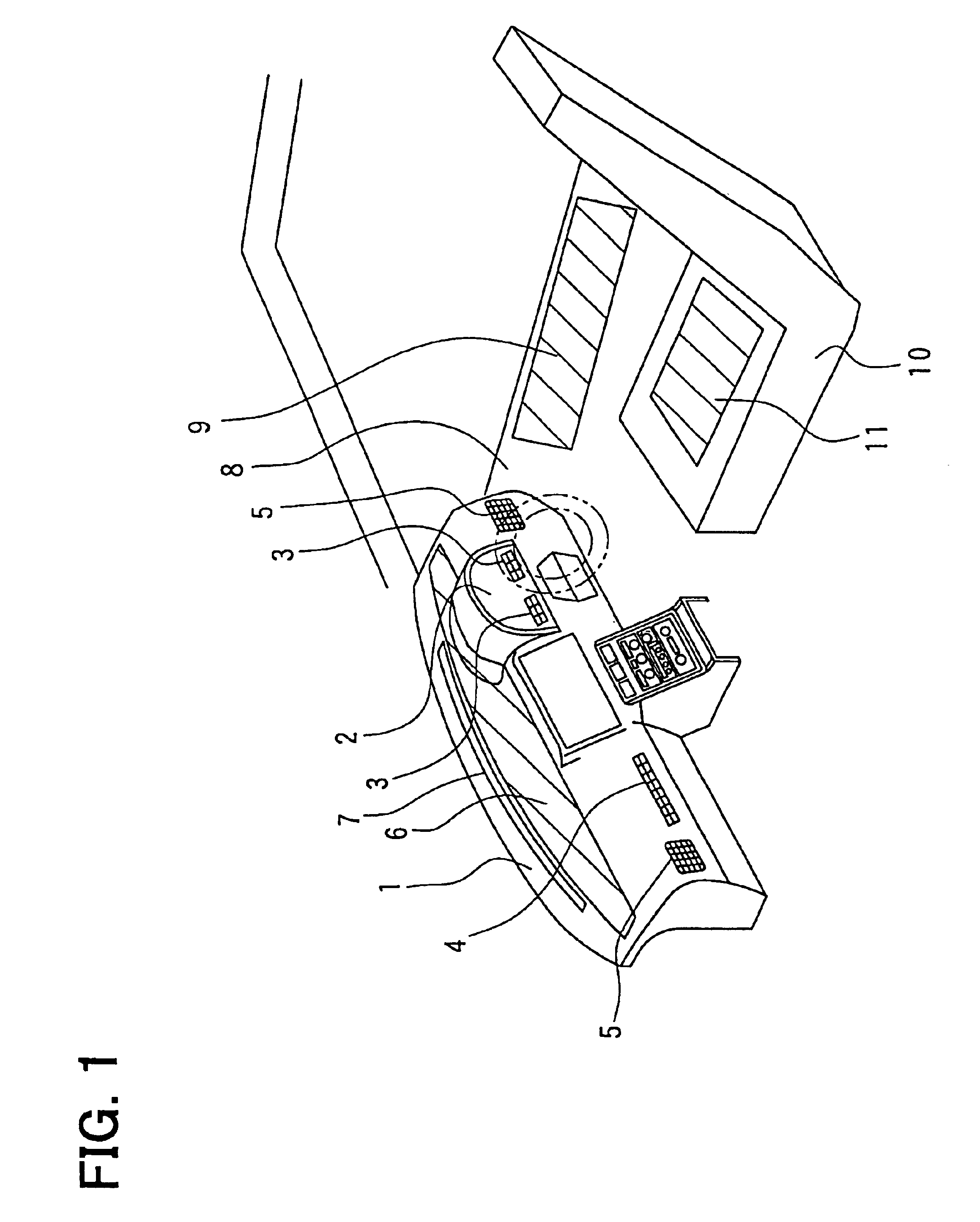
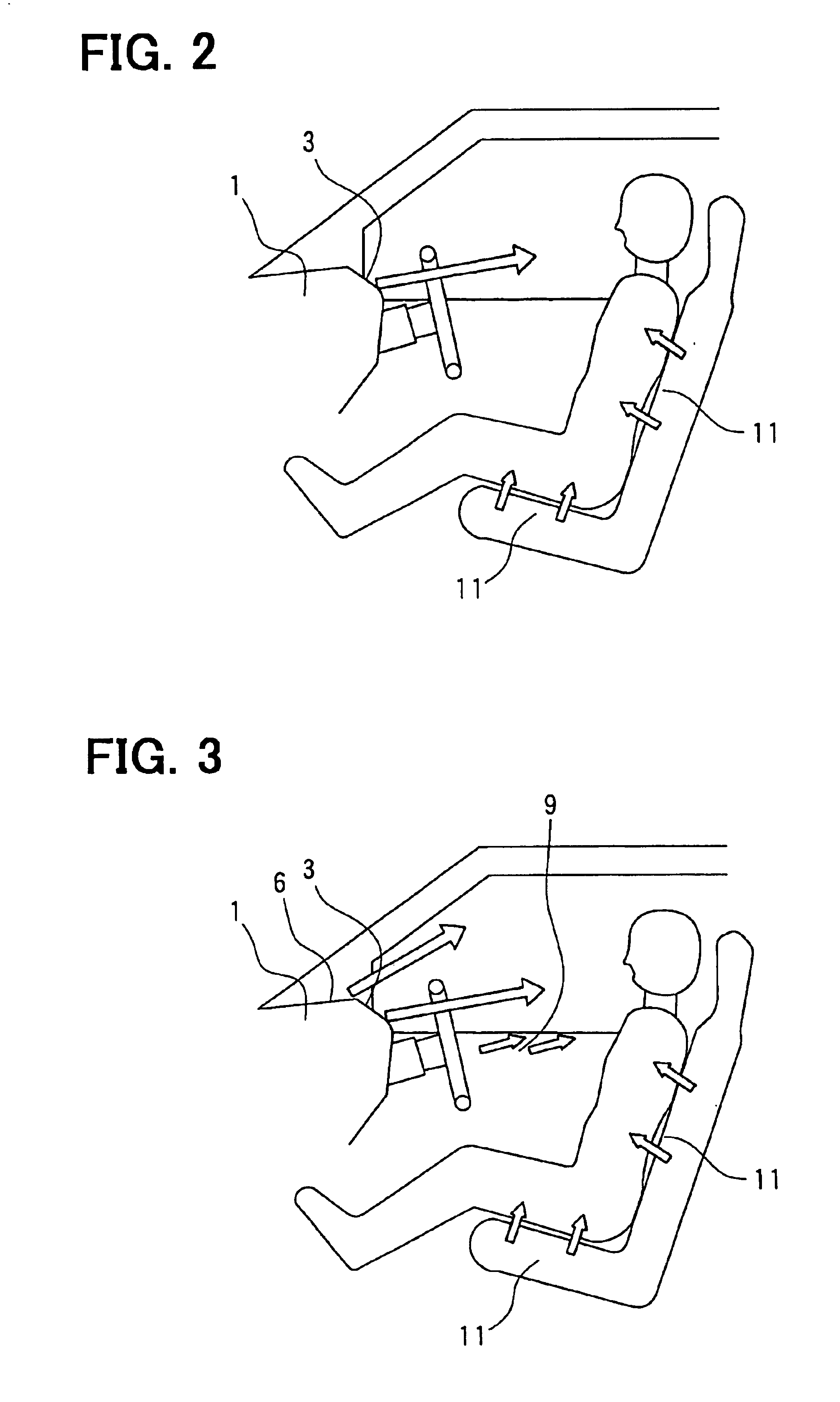
A vehicle air conditioner according to the first embodiment will be described with reference to FIGS. 1-5. As shown in FIG. 1, an instrument panel portion 2 having a meter member such as a speed meter is provided in a dashboard 1 extending in a vehicle width direction (vehicle right-left direction), at a driver's seat side. An air conditioning unit (not shown), for controlling a temperature and a humidity of air to be blown into a passenger compartment, is provided in the dashboard 1 at a front passenger's seat side next to the driver's seat in the vehicle width direction.

The air conditioning unit is a general air conditioning unit including a cooling heat exchanger such as an evaporator for cooling air, a heating heat exchanger such as a heater core for heating air after passing through the cooling heat exchanger, a temperature adjustment unit for adjusting an air heating amount in the heating heat exchanger so that conditioned air having a predetermined temperature is obtained, an...

second embodiment

The second embodiment of the present invention will be described with reference to FIGS. 6-8. In the above-described first embodiment of the present invention, the instrument panel air outlet 6 and the door air outlet 9 are used as the indirect air outlet. However, in the second embodiment, a ceiling air outlet 12 shown in FIG. 7 is also provided as the indirect air outlet. In the second embodiment, the other parts air similar to those of the above-described first embodiment.

A conditioned-air blowing state in the initial stage of the cool down operation is shown in FIG. 6. In the initial stage of the cool down operation, as shown in FIG. 6, conditioned air (cool air) is directly blown from the seat air outlet 11 and the face air outlets such as the meter air outlet 3 and the passenger's seat side face air outlet 4, similarly to that in the above-described first embodiment. The later stage of the cool down operation is shown in FIG. 7. In the later stage of the cool down operation, t...

third embodiment

In the above-described first embodiment, the face air outlet used as the direct air outlet includes the meter air outlet 3 and the passenger's seat side face air outlet 4. In the third embodiment, the meter face air outlet 3 and the passenger face air outlet 4 are eliminated. Instead of the direct air outlets 3, 4, as shown in FIG. 9, a center face air outlet 13 is provided substantially in a center area of the dashboard 1 in the vehicle width direction, to be used as the direct air outlet. In the third embodiment, the other parts are similar to those of the above-described first embodiment, and advantages described above can be obtained.


PUM


Abstract

In an initial stage of a cool down operation of a vehicle air conditioner, a rapid cooling operation is performed while cool air is directly blown to a passenger from direct air outlets. In a later stage of the cool down operation of the vehicle air conditioner, a temperature of an inner wall portion of a passenger compartment is reduced while cool air is indirectly supplied to the passenger of the passenger compartment from the indirect air outlet. Accordingly, cool air can be locally blown to the passenger in the initial stage, and cool air can be supplied to the entire passenger compartment while restricting an adverse effect due to heat radiation of the inner wall portion in the later stage. Thus, operation performance of the air conditioner can be improved while comfortable air conditioning feeling can be given to the passenger in the passenger compartment.

Description

This application is related to and claims priority from Japanese Patent Applications No. 2002-336553 filed on Nov. 20, 2002 and No. 2002-339242 filed on Nov. 22, 2002, the contents of which are hereby incorporated by reference.1. Field of the InventionThe present invention relates to a vehicle air conditioner that has a direct air outlet for blowing conditioned air directly toward a passenger in a passenger compartment and an indirect air outlet for blowing conditioned air indirectly toward the passenger in the passenger compartment.2. Description of Related ArtIn a vehicle air conditioner described in JP-A-1-285417(corresponding to U.S. Pat. No. 4,938,033), a cooling operation for cooling a passenger compartment is performed to have three operation stages, that is, a rapid cooling stage (cool down stage), a stationary cooling stage, and a transient cooling stage between the rapid cooling stage and the stationary cooling stage. Further, an air outlet mode is changed in accordance wi...

Claims


Application Information

Patent Timeline
Patent Type & Authority Patents(United States)
IPC IPC(8): B60H1/24B60H1/00
CPCB60H1/00207B60H1/00842B60H1/247
Inventor SHIKATA, KAZUSHIKAMIYA, TOMOHIROUM BAYASHI, MAK TOINADA, TOMOHIRO
Owner DENSO CORP
Why Eureka
Try Eureka