Sensor for sensing absolute angular position of a rotatable body

a technology of angular position and sensor, which is applied in the direction of instruments, force/torque/work measurement apparatus, material analysis, etc., can solve the problems of space and cost, slowness and more prone to error, and device is prone to error

Inactive Publication Date: 2004-07-06
BISHOP INNOVATION PTY LTD
View PDF24 Cites 84 Cited by
  • Summary
  • Abstract
  • Description
  • Claims
  • Application Information

AI Technical Summary

Problems solved by technology

Generally, the use of a torsion bar requires the use of a failsafe mechanism, being a torque limiting device to prevent failure of the torsion bar when unavoidable torque overload conditions occur.
In the latter case it is necessary to count successive changes of EMR intensity incident on the photo-detector, which is slower and more prone to error.
This device is prone to error due to misalignment and bending load and requires a collimated and monochromatic source of EMR.
The regions of high and low reflectivity can be arranged axially or radially about the axis of rotation of the shaft, and are of such a nature that allows a continuous output of the arrays at any instant in time regardless of the angular position of the shaft, as the limited array dimensions may not allow the complete circumference or radial face to be viewed by the arrays.
Firstly, the use of reflective grating elements allows simpler and more compact construction by the use of a cylindrical grating element arrangement, which is not readily achievable using disc apertures as shown in the prior art without requiring a significantly increased diameter. It also allows the EMR source(s) and array(s) to be packaged in the same assembly with further savings in space and cost.
Secondly, it allows for easy assembly and disassembly of the transducer, as the grating elements can be removed from one end of the transducer in an axial direction without disturbing the EMR source(s) or array(s).
Thirdly, another advantage with the use of reflective grating elements is that the EMR is reflected from the surface, and is not affected by edge scattering as is the case with apertures with a non-zero thickness. Such scattering limits the maximum resolution of the device.
Fourthly, the use of reflective grating elements allows the use of well known and accurate photographic or metallising techniques, for example metal on glass. The use of these techniques with apertures may result in loss of resolution or other problems from internal reflection, diffraction or degradation over time as the EMR has to travel through the glass between the metallised regions.

Method used


Image

  • Sensor for sensing absolute angular position of a rotatable body
  • Sensor for sensing absolute angular position of a rotatable body
  • Sensor for sensing absolute angular position of a rotatable body

Examples


first embodiment

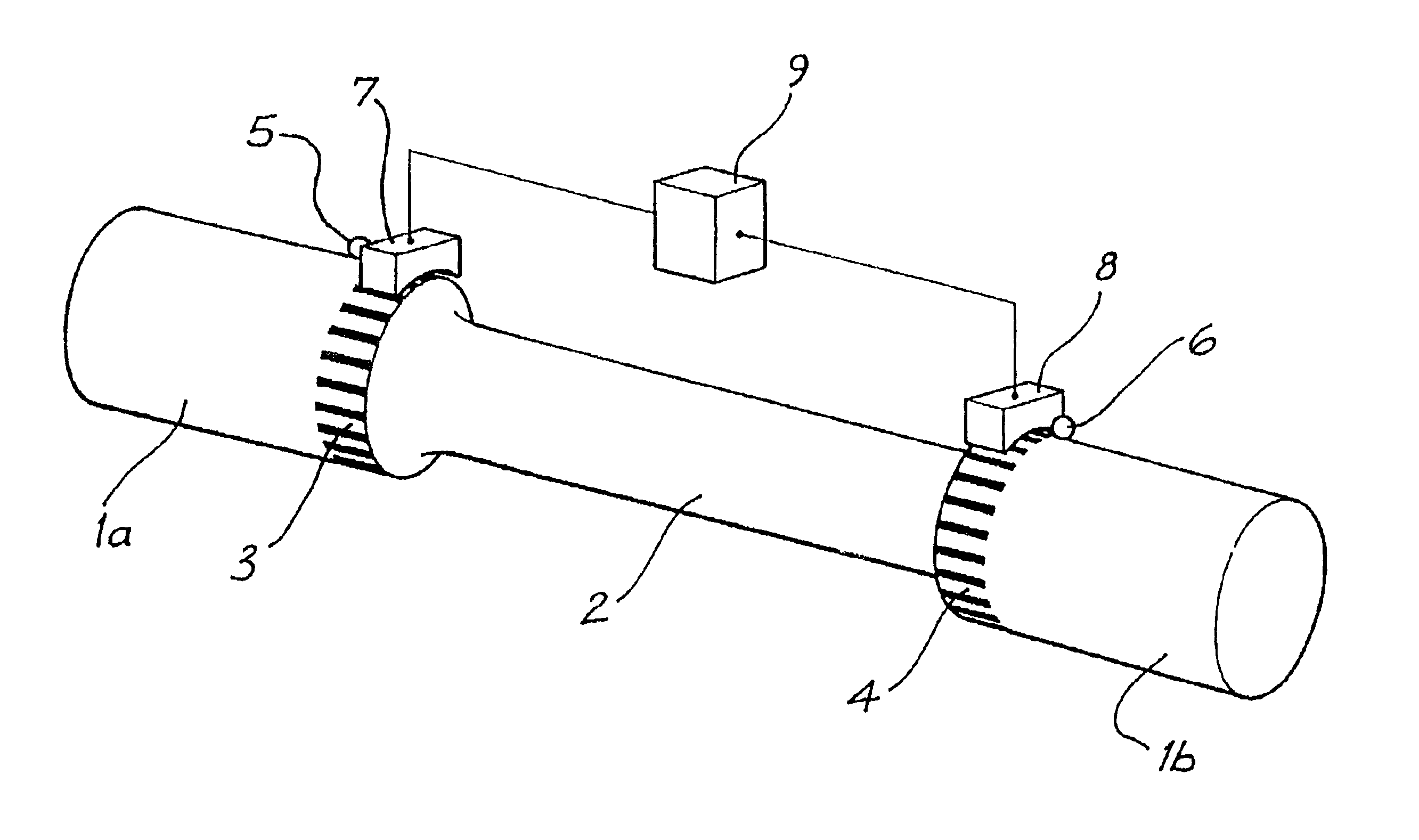
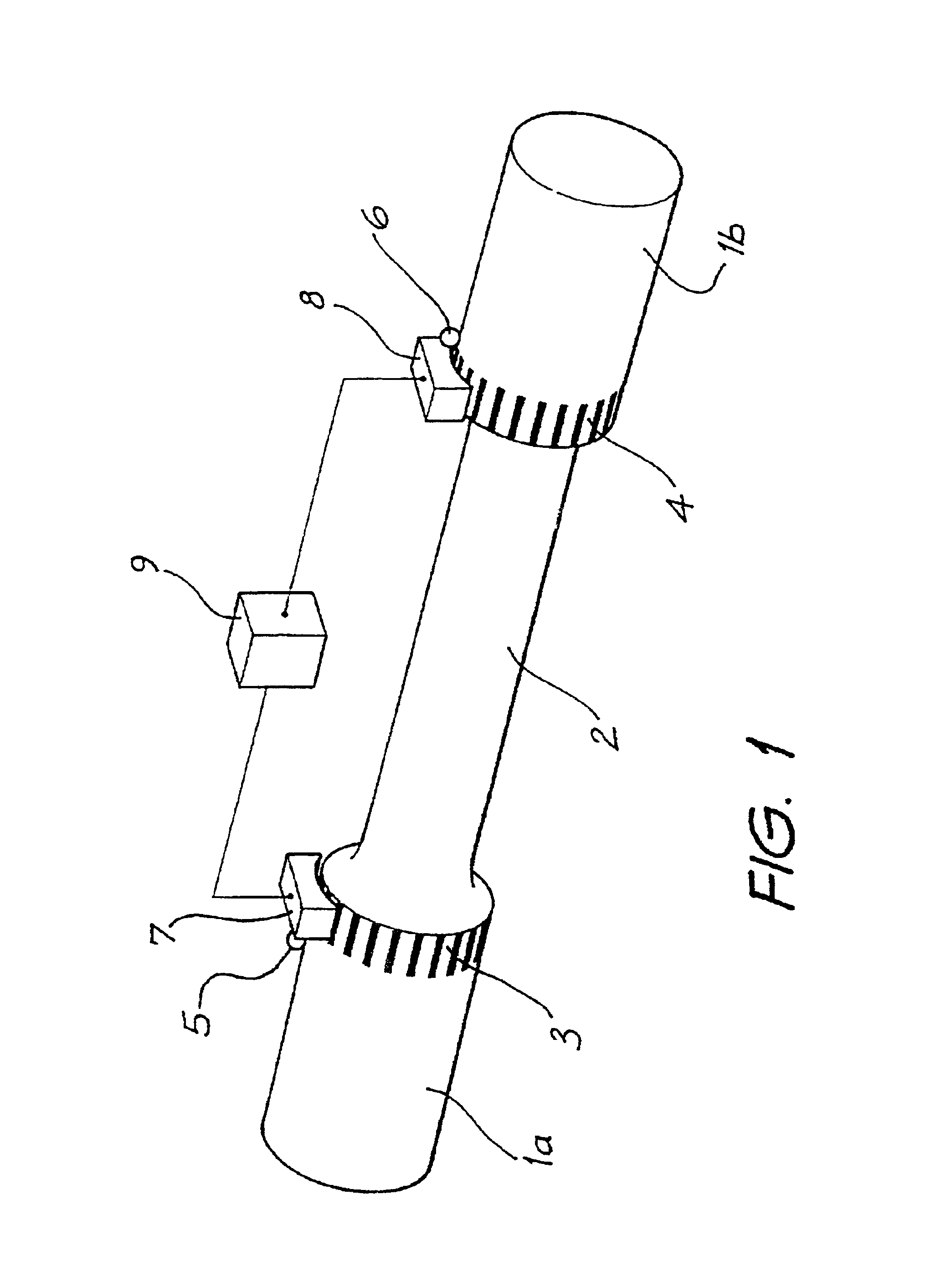
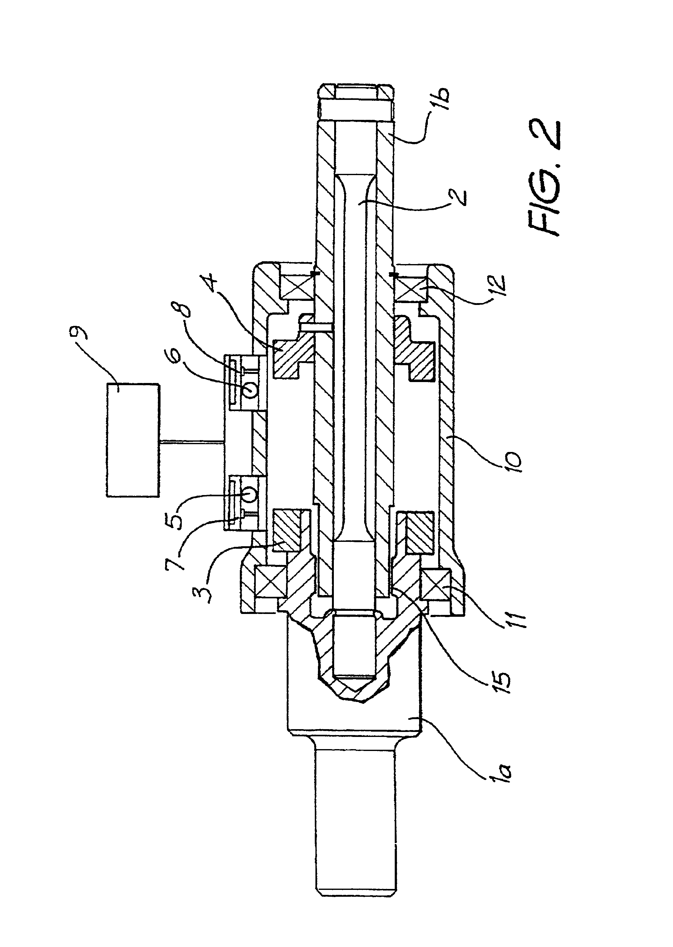
FIG. 2 shows a cross section of a torque transducer according to the present invention, using the principles shown in FIG. 1. Cylindrical grating elements 3 and 4, comprising surfaces composed of alternating high and low reflectivity, are attached to torque input members 1a and 1b which are connected to either end of the torsion bar 2. In other (not shown) embodiments either (or both) grating elements may be integral with their respective torque input members. The assembly is enclosed in housing 10 and supported by bearings 11 and 12. EMR sources 5 and 6 are disposed to illuminate the surfaces. Arrays 7 and 8 of detectors receive incident EMR from the surfaces and the patterns thus generated on the arrays are processed by a processor 9 to provide a measurement of torque. When torque is applied between torque input members 1a and 1b torsion bar 2 angularly deflects, resulting in a displacement of one pattern with respect to the other. Failsafe mechanism 15 limits the maximum torque c...

second embodiment

FIGS. 4, 5 and 6 shows the present invention. Cylindrical grating elements 21 and 22 are attached to torque input members 1a and 1b, connected to either end of the torsion bar 2. The outer cylindrical surfaces of grating elements 21 and 22 are discontinuous and are formed in part by substantially axially aligned, radially protruding castellations 13 and 14 respectively. The regions of high reflectivity correspond to the areas of maximum radius of the castellations with respect to their mutual central axis 16, that is outer peripheral areas 13a and 14a respectively, and may be smoothly machined, moulded or sintered, or surface treated with paint or material deposition to impart the required high reflectivity. The regions of low reflectivity are angularly aligned with the discontinuous gap areas of the outer cylindrical surfaces of grating elements 21 and 22, namely areas 13b and 14b respectively and, in the embodiment shown here, are substantially non-reflective due to the presence o...

fourth embodiment

FIGS. 10 and 11 show the present invention. Grating elements 29 and 30, again respectively attached to torque input members 1b and 1a, incorporate continuous, radially disposed surfaces 23 and 24. These radially disposed surfaces are arranged perpendicular to, and have a mutual central axis collinear with, axis of rotation 16. Each surface comprises substantially radially disposed alternating regions of high and low reflectivity 27 and 28 respectively. Grating elements 29 and 30 are surrounded by housing 10 and the assembly carried in bearings 11 and 12. EMR sources 31 and 32 are disposed to illuminate the surfaces. Arrays 33 and 34 of detectors receive incident EMR from the surfaces and the patterns thus generated on the arrays are processed by processor 9. When torque is applied between torque input members 1a and 1b, torsion bar 2 angularly deflects, resulting in a displacement of one pattern with respect to the other. Failsafe mechanism 15, shown in cross section in FIG. 7, limi...


PUM

PropertyMeasurementUnit
angleaaaaaaaaaa
angleaaaaaaaaaa
lengthaaaaaaaaaa

Abstract

An angle sensor for sensing the absolute angular position of a rotatable body, such as a rotating shaft of an electric power steering system for an automobile, is disclosed.

Description

This invention relates to an angle sensor for sensing the absolute angular position of a rotatable body, and in particular a rotating shaft such as found in electric power steering systems in vehicle applications.Electric power steering systems conventionally incorporate an input shaft element, connected via an intermediate shaft and Hookes joint arrangement to the steering wheel. The input shaft therefore needs to rotate through an angle typically one to two revolutions either side of the on-centre steering position. The input shaft is at least partially surrounded by the fixed housing of the steering gear. It is a requirement of the electric power steering servo system to accurately measure the continuously varying torque in this rotating shaft. Conventionally torque applied to the shaft causes it to angularly deflect, such deflection causing one part of the shaft to angularly displace with respect to another part, and this displacement is sensed to provide a measurement of this t...

Claims


Application Information

Patent Timeline
Patent Type & Authority Patents(United States)
IPC IPC(8): G01L5/22G01L3/12G01D5/347G01D5/26
CPCG01D5/3473G01D5/34776G01L3/12G01L5/221
Inventor BAXTER, JOHNEISENHAUER, KARL YARNOS
Owner BISHOP INNOVATION PTY LTD
Why Eureka
Try Eureka