
Process for generation of engraving data

a technology of engraving data and process, applied in the field of engraving data generation, can solve the problems of loss of reproduction accuracy, blurred or irregular fine line patterns and fonts, and unwanted color effects,

Inactive Publication Date: 2004-07-13
MDC MAX DATWYLER BLEIENBACH AG
View PDF12 Cites 3 Cited by
  • Summary
  • Abstract
  • Description
  • Claims
  • Application Information

AI Technical Summary

Benefits of technology

To further improve printing results the working screen can be matched to the dimensions of the copies (for example the individual label). Also here stretching or flattening of the screen geometry is used.

Problems solved by technology

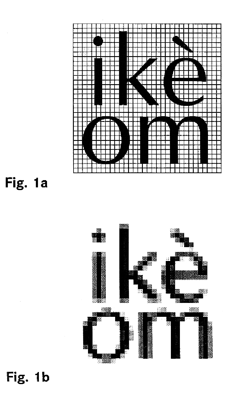
It is apparent that in the transition from a high resolution bit map to the stipulated screen density a loss of reproduction accuracy must be tolerated.
In practice this often leads to fine line patterns and fonts becoming blurred or irregular in the sense of a Moire effect.
In multicolor print products therefore on the line boundaries unwanted color effects can arise because based on the different color screens different line boundaries cannot be avoided.

Method used


Image

  • Process for generation of engraving data
  • Process for generation of engraving data
  • Process for generation of engraving data

Examples


Embodiment Construction

The object of the invention is to devise a process of the initially mentioned type which ensures the highest possible image quality ("sharpness", "color precision") even in finely structured printer's copies.

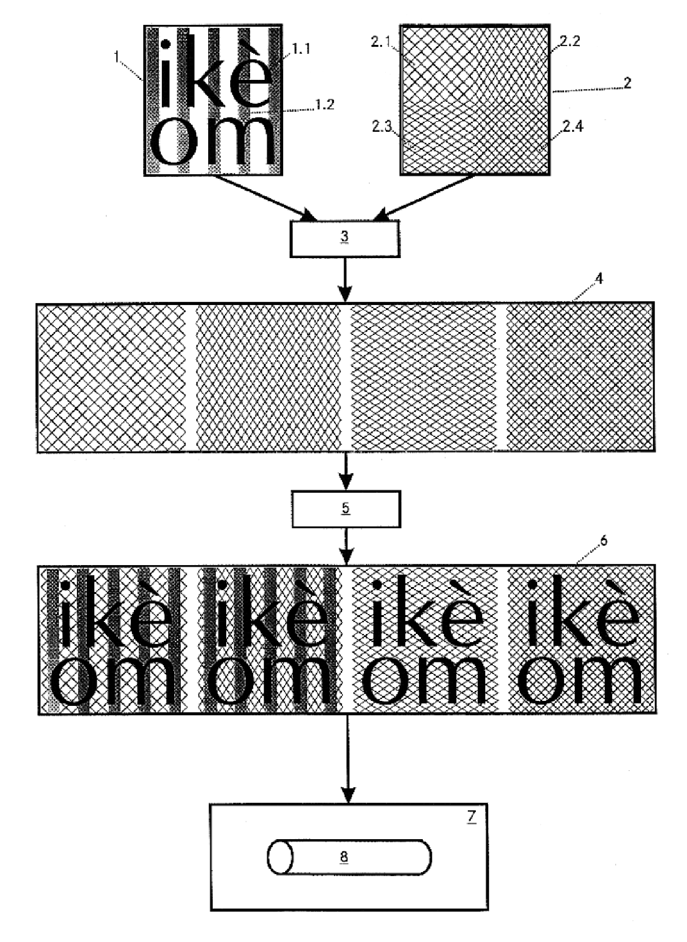
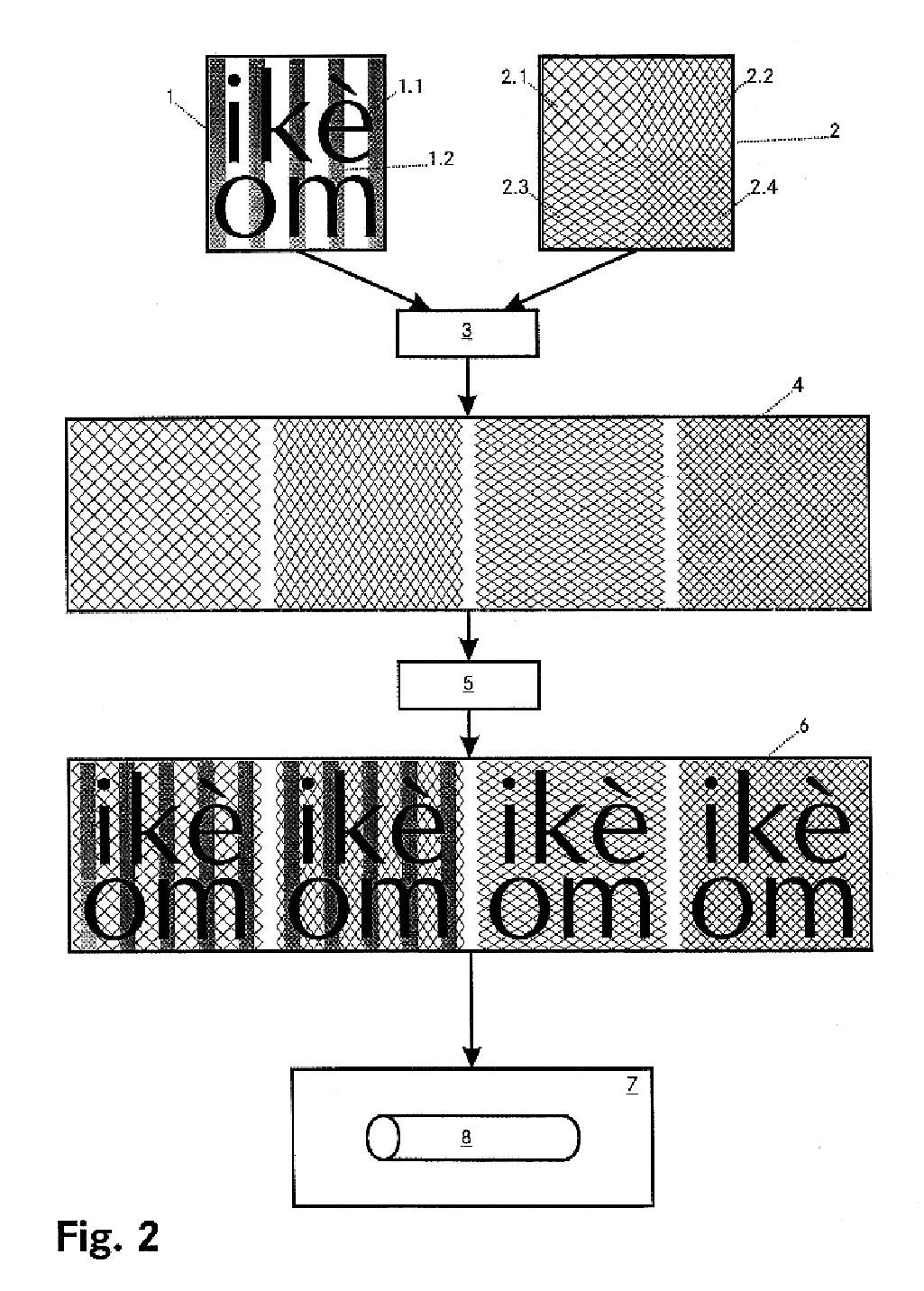
The object is achieved by the features of claim 1. As claimed in the invention not simply the stipulated print density (screen fineness) is used (as is actually expected or required by the client). Rather around a stipulated print density a variation range is defined and then within this range depending on the geometry of the elements contained in the actual printer's copy an optimally matched screen is determined.

The invention is not concerned with simply choosing the finest possible screen within the (pre-)defined variation range. Depending on the type of geometry (for example, periodicity of a line pattern) it can be that a slightly coarser screen coincides with the geometry (for example periodicity) and thus allows a image of maximum sharpness. Here it is important that the ...


PUM


Abstract

To generate engraving data (6), especially for an engraving cylinder, based on a vectorized printer's copy (1) and a screen stipulation (2), depending on the geometry of the elements contained in the printer's copy, within predefined variation range for the engraving data (6) at least one working screen (4) is chosen which deviates from the screen stipulation (2). In the printer's copy (1) first at least one line element is chosen. Afterwards within the variation range a working screen is determined which is matched to the periodicity of the determined line element with respect to density and / or angle. Then in the printer's copy (1) font elements are chosen and they are matched to the working screen using font hinting data. If necessary also the screen geometries which belong to the different process colors are stretched or flattened in the line direction and / or in the advance direction in order to be aligned to the chosen line element.

Description

TECHNICAL DOMAINThe invention relates to a process for generation of engraving data, especially for an engraving cylinder, based on a vectorized printer's copy and a screen stipulation. Furthermore the invention relates to a device for engraving of a engraving cylinder according to the engraving data generated using the process.PRIOR ARTElectro-mechanical engraving of printing forms has been possible at latest since the 1970s with high precision and reliability. Here it is known (compare for example EP 0 056 829 B1) that in four color printing the screens of the different colors must be matched to one another such that no visible color shifts occur (color drift).In the production of engraving data (i.e the data with which the engraving machines are triggered to machine the engraving cylinder) from a digitally stored printer's copy, conventionally first a high definition bit map is produced to undertake reduction to the screen density stipulated by the client.It is apparent that in t...

Claims


Application Information

Patent Timeline
Patent Type & Authority Patents(United States)
IPC IPC(8): B41B19/00G06K15/02B44B3/00B44C1/22B41C1/045
CPCB41B19/00G06K15/02G06K2215/0037
Inventor SCHULTZE, STEFANDENZLER, URSFUNK, PETER
Owner MDC MAX DATWYLER BLEIENBACH AG
Learn More