Method and system for controlling a robot

a robot and radio transceiver technology, applied in the field of robots, can solve the problems of not being able to reach the standard radio transceiver attached to the moving robot, the radio signals sent from the standard radio transceiver cannot penetrate a certain wall or floor of the building, and it is difficult for the moving robot to maintain contact with the control station using a standard radio transceiver,

Inactive Publication Date: 2004-07-13
HUMATICS CORP
View PDF27 Cites 271 Cited by
  • Summary
  • Abstract
  • Description
  • Claims
  • Application Information

AI Technical Summary

Problems solved by technology

In the robotics field, one of the most significant design challenges involves the development of new ways to improve the way a control station can interact with and control the actions of a robot.
Unfortunately, problems have arisen in the past with the use of standard radio equipment because there are often problematical "dead zones" within a building that may interfere with the communications between the control station and a moving robot.
Dead zones are caused by the closed structure of the building, which can make it difficult for a moving robot using a standard radio transceiver to maintain contact with a control station using a standard radio transceiver.
For instance, the standard radio signals sent from the standard radio transceiver attached to the control station may not be able to penetrate a certain wall or floor within the building and as such may not reach the standard radio transceiver attached to the moving robot.
The closed structure of the building may also cause "multipath interference" which can interfere with standard radio transmissions between the control station and the robot.
Multipath interference is an error caused by the interference of a standard radio signal that has reached a standard radio receiver by two or more paths.
For instance, the standard radio receiver attached to the robot may not be able to demodulate a received radio signal because the originally transmitted radio signal effectively cancels itself out by bouncing of walls and floors of the building before reaching the robot.
Such codes are commonly referred to as time-hopping codes or pseudo-noise (PN) codes since their use typically causes inter-pulse spacing to have a seemingly random nature.
band. It can also be observed from FIG. 2A that impulse transmission systems typically have very low average duty cycles, resulting in average power lower than peak
As the number of coincidences increases, the propensity for data errors increases.
Generally, keeping the number of pulse collisions minimal represents a substantial attenuation of the unwanted signal.
Such `random-like` codes are attractive for certain applications since they tend to spread spectral energy over multiple frequencies while having `good enough` correlation properties, whereas designed codes may have superior correlation properties but possess less suitable spectral properties.
Impulse radio systems operating within close proximity to each other may cause mutual interference.
While coding minimizes mutual interference, the probability of pulse collisions increases as the number of coexisting impulse radio systems rises.
Additionally, various other signals may be present that cause interference.
However, when the transmitted impulse signal is coded and the impulse radio receiver template signal 506 is synchronized using the identical code, the receiver samples the interfering signals non-uniformly.
Multipath fading effects are most adverse where a direct path signal is weak relative to multipath signals, which represents the majority of the potential coverage area of a radio system.
This characteristic has been the subject of much research and can be partially improved by such techniques as antenna and frequency diversity, but these techniques result in additional complexity and cost.
Narrow band systems, on the other hand, are limited to the modulation envelope and cannot easily distinguish precisely which RF cycle is associated with each data bit because the cycle-to-cycle amplitude differences are so small they are masked by link or system noise.

Method used


Image

  • Method and system for controlling a robot
  • Method and system for controlling a robot
  • Method and system for controlling a robot

Examples


Embodiment Construction

Referring to FIGS. 9-25, there are disclosed several embodiments of an exemplary system 900, an exemplary robot 902 and preferred method 1300 in accordance with the present invention. Although the present invention is described as using impulse radio technology, it should be understood that the present invention can be used with any type of ultra wideband technology, but is especially suited for use with time-modulated ultra wideband technology. Accordingly, the system 900, the robot 902 and the preferred method 1300 should not be construed in a limited manner.

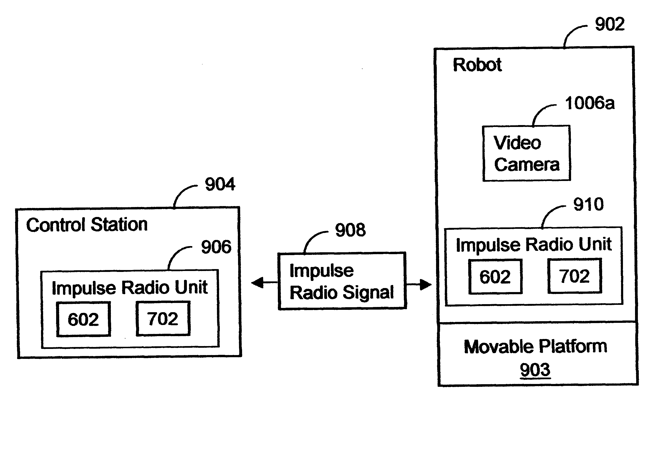
Referring to FIG. 9, there is a diagram illustrating the basic components of the system 900 in accordance with the present invention. The system 900 includes a control station 904 that has a first impulse radio unit 906 which operates to transmit and receive impulse radio signals 908 to and from a second impulse radio unit 910 attached to the robot 902 (only one shown). The impulse radio signals 908 convey information using a ...


PUM


Abstract

A system and method are described that use impulse radio technology to enhance the capabilities of a robot. In one embodiment, a system, a robot and a method are provided that use the communication capabilities of impulse radio technology to help a control station better control the actions of the robot. In another embodiment, a system, a robot and a method are provided that use the communication, position and / or radar capabilities of impulse radio technology to help a control station better control the actions of a robot in order to, for example, monitor and control the environment within a building.

Description

1. Field of the InventionThe present invention relates in general to robots and, in particular, to a system and method capable of using impulse radio technology to enhance the capabilities of a robot.2. Description of Related ArtIn the robotics field, one of the most significant design challenges involves the development of new ways to improve the way a control station can interact with and control the actions of a robot. To date many control stations have a standard radio transceiver, which transmits and receives radio signals to and from another standard radio transceiver attached to the robot in order to interact with and control the actions of that robot. Unfortunately, problems have arisen in the past with the use of standard radio equipment because there are often problematical "dead zones" within a building that may interfere with the communications between the control station and a moving robot. Dead zones are caused by the closed structure of the building, which can make it...

Claims


Application Information

Patent Timeline
Patent Type & Authority Patents(United States)
IPC IPC(8): B25J9/16B25J9/18G05D1/02G06F19/00
CPCB25J9/1689G05D1/0282G05B2219/33192G05B2219/40161G05D1/0246G05D1/0274G05D2201/0207G05D2201/0209
Inventor GLENN, SUSAN J.SHREVE, GREGORY A.
Owner HUMATICS CORP
Why Eureka
Try Eureka