Method and device for multi-user channel estimation

a multi-user channel and estimation method technology, applied in the field of wireless communication systems, can solve the problems of limiting the achievable performance and capacity of a communication system, severely distorting the received signal, and maximizing system capacity and performan

Inactive Publication Date: 2004-07-20
MOTOROLA SOLUTIONS INC
View PDF6 Cites 248 Cited by
  • Summary
  • Abstract
  • Description
  • Claims
  • Application Information

AI Technical Summary

Problems solved by technology

In a wireless communication system, a major design challenge is to maximize system capacity and performance in the presence of interference and a time-varying multipath channel.
Interference and multipath are major factors that limit the achievable performance and capacity of a communication system because both effects interfere with the ability of a communication receiver to properly decode the transmitted data.
The presence of multipath can severely distort the received signal.
In a multipath environment, the multiple copies of the transmitted signal can interfere constructively in some portions of the occupied bandwidth.
In other portions of the occupied bandwidth, the multiple copies can interfere destructively at the receiver.
This interference causes unwanted variations in the received signal strength over the bandwidth occupied by the signal.
Furthermore, if the difference in the path delays of the various propagation paths is significantly greater than the duration of a transmitted information symbol, then intersymbol interference is present at the receiver.
The demodulation process (the process of determining which information symbol was transmitted) becomes difficult in the presence of intersymbol interference.
In addition to multipath, interference is another system component that limits the performance of a communication system.
If the system is deployed in an unlicensed band, then interference can be generated by other users of the band.
A cellular system employing a large reuse factor does not utilize the allocated spectrum as efficiently as a cellular system employing a smaller reuse factor.
However, the level of co-channel interference received by a receiver in the cellular system is directly dependent on the reuse factor.
Reducing the reuse factor while maintaining the same transmit power tends to increase the level of co-channel interference experienced by a receiver.
Algorithms known in the art that do not adequately track the time-varying frequency response of the received signal will exhibit poor interference suppression performance and poor equalization performance.
Failure to track these variations will reduce the ability of the receiver to demodulate the signals transmitted by the multiple subscriber devices.
One final problem faced in a communications receiver is the amount of operations (e.g., complex multiplies) that its processors can perform per second.

Method used


Image

  • Method and device for multi-user channel estimation
  • Method and device for multi-user channel estimation
  • Method and device for multi-user channel estimation

Examples


first embodiment

For the reduced complexity channel estimator, we assume that the existing channel estimator for user j on subcarrier k at time block b can be expressed in the following form:

H.sub.j (k,b)=YE.sub.j (k,b) (37)

where H.sub.j (k,b) is a M.times.1 vector of the auxiliary frequency-domain channel gains for user j at subcarrier k and time block b, Y is the M.times.P matrix of received pilot data, and E.sub.j (k,b) is a primary weighting matrix of the existing channel estimator. The present invention finds a P.times.L matrix (referred to as the frequency to reduced time weighting coefficients), Q.sub.j (b), that is a function of the primary weighing coefficients, that when multiplied by the received pilot data will give a set of time-domain channel gains that completely parameterize the frequency-domain channel on time block b. The set of time-domain channel gains are then FFT'd (or similarly transformed) into the frequency-domain to get the set of frequency-domain channel estimates. Due to ...

second embodiment

the reduced complexity estimator works by parameterizing each tap corresponding to a single lag value n or subcarrier k=n (represented by the entries in h.sub.j (n,b)) by the IDFT of a small number of frequency-domain taps (referred to as Doppler taps). This is done akin to the above parameterization by parameterizing the time-varying h.sub.j,m (n,b) of user j on antenna m by V.sub.T =(2V+1) time-invariant "Doppler" channels, g.sub.j,m,v (n) (v=-V, . . . ,+V) as given in the following equation: ##EQU27##

where c(b) and g.sub.j,m (n) are V.sub.T.times.1 vectors defined as: ##EQU28##

We assume that the existing channel estimator can be expressed in the following form:

h.sub.j (b)=YQ.sub.j (b) (48)

where Y is a M.times.P matrix of received pilot data, Q.sub.j (b) is the existing channel estimator (in the preferred embodiment, this is the same Q.sub.j (b) as in Equation (44)), and:

h.sub.j (b)=[h.sub.j (0,b).vertline. . . . .vertline.h.sub.j (L-1,b)] (49)

The "Doppler" channels are found by s...

third embodiment

the reduced complexity estimator is a combination of the first and second ways. This is done by using the Q.sub.j (b) of Equation (44) in Equation (48). Here Z.sub.j,l is referred to as the reduced time to reduced frequency weighting coefficients. The computational complexity for the Doppler channel parameterization of the existing channel estimator in number of complex multiplies is (for the above example with V=1, V.sub.T =3): JV.sub.T M(PL+(N / 2)log .sub.2 (N))=5,706,288. This has 163.5 times less complex multiplies than the frequency-domain existing channel estimator and 2.67 times fewer complex multiplies than the time-domain only parameterization of the existing channel estimator with nearly identical performance.

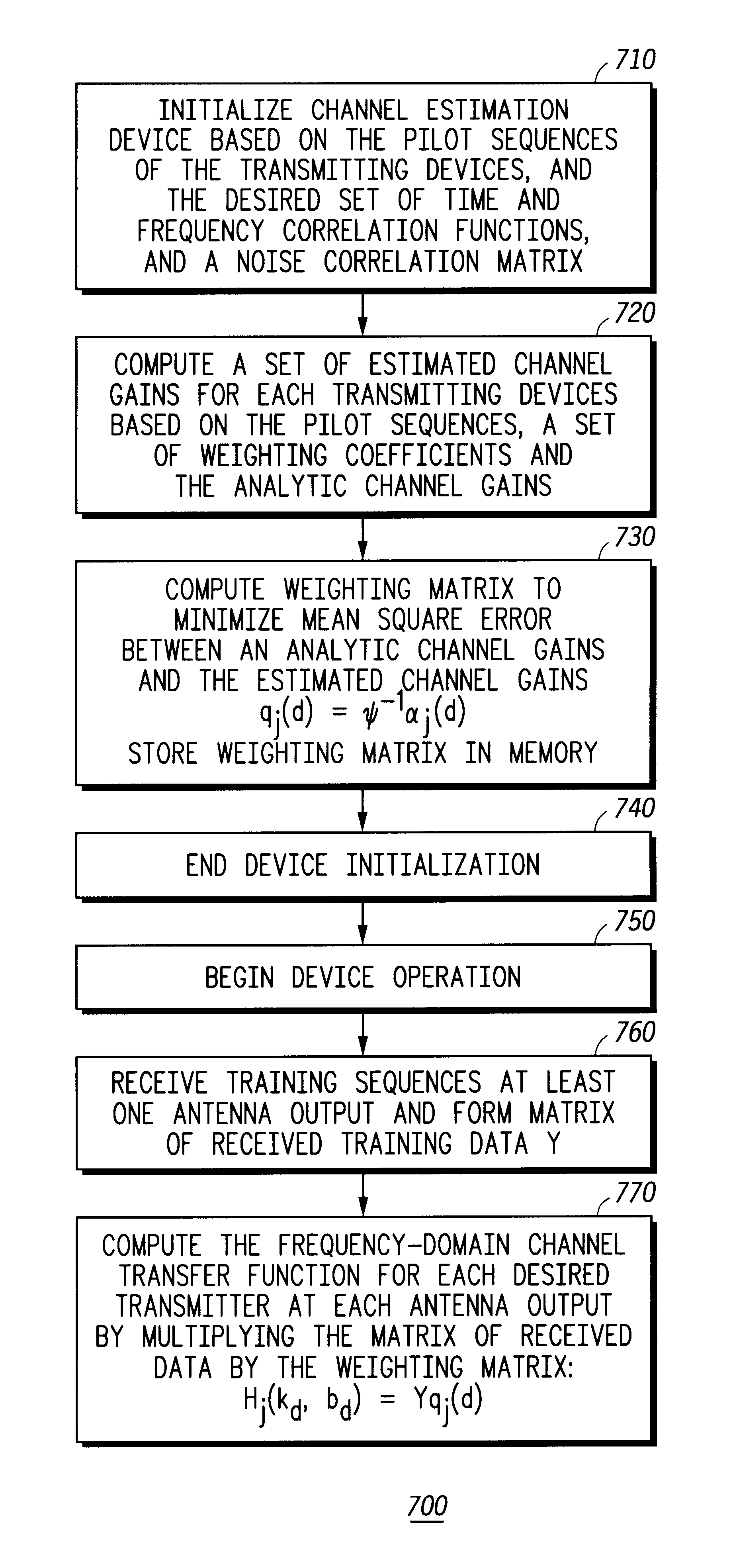
FIG. 7 is a flow chart representation of the method performed by a preferred embodiment of the channel estimation device of 500 to compute the channel gain between at least one transmitting device and at least one receiving antenna in accordance with the present invent...


PUM


Abstract

The invention computes frequency-domain channel gains by compiling a set of estimated channel gains as a function of pilot sequences, a set of analytical channel gains variables, and a set of weighting coefficients variables. A plurality of weighting coefficients are computed as a function of time and frequency correlation functions, a noise correlation matrix, and pilot sequences. A weighting matrix is computed from the weighting coefficients. After receiving a training sequence from at least one transmitter, a received data matrix is computed from the training sequence. The weighting matrix and the received data matrix are used to compute the frequency-domain channel gains. The invention also provides a method for reducing the computational complexity of estimating the time and frequency response of at least one desired signal received by at least one antenna. Also, the time and frequency response of at least one desired signal received by at least one antenna can be both interpolated and predicted with the present invention.

Description

The present invention generally relates to the field of communication systems and more particularly, to estimating the time and frequency response of at least one desired signal received by at least one antenna and reducing the computational complexity of estimating the time and frequency response of at least one desired signal received by at least one antenna, interpolating the time and frequency response of at least one desired signal received by at least one antenna, and predicting the time and frequency response of at least one desired signal received by at least one antenna.BACKGROUND OF INVENTIONIn a wireless communication system, a major design challenge is to maximize system capacity and performance in the presence of interference and a time-varying multipath channel. Multipath propagation is caused by the transmitted signal reflecting off objects near the transmitter and receiver and arriving at the receiver over multiple paths. Interference in a communication system can co...

Claims


Application Information

Patent Timeline
Patent Type & Authority Patents(United States)
IPC IPC(8): H04L1/02H04L1/06H04L25/02
CPCH04L1/06H04L25/022H04L25/0224H04L25/0206H04L25/0204
Inventor VOOK, FREDERICK W.THOMAS, TIMOTHY A.
Owner MOTOROLA SOLUTIONS INC
Why Eureka
Try Eureka