Exhaust gas purifying system for internal combustion engine

a technology for exhaust gas purification and internal combustion engines, which is applied in the direction of separation process, auxillary pretreatment, filtration separation, etc., can solve the problems of hindering equipment downsizing, difficult to manufacture a carrier with a remarkably large cross-sectional shape, and still remains a problem to be solved

Inactive Publication Date: 2004-07-27
KOMATSU LTD
View PDF2 Cites 53 Cited by
  • Summary
  • Abstract
  • Description
  • Claims
  • Application Information

AI Technical Summary

Benefits of technology

In the above-described exhaust gas purifying system, although the carriers are arranged in series, the exhaust gas passing through a different distribution flow path flows in each of the carriers. Therefore, the capacity of the whole of the carriers increases substantially a plurality of times as in the case of the carriers arranged in parallel, so that the inherent function as an exhaust gas purifying system is improved.
According to the above-described exhaust gas purifying system, since the inlet pipe and the outlet pipe are installed substantially at right angles with the flow direction of exhaust gas in the carrier, the layout of the inlet pipe and the outlet pipe is accomplished easily. Therefore, the exhaust gas purifying system can be made more compact, and can be installed in a smaller installation space.

Problems solved by technology

Such a carrier has many limitations in manufacturing, so that it is difficult to manufacture a carrier having a remarkably large cross-sectional shape.
However, if a plurality of carriers are arranged in parallel, the cross-sectional area of the whole carrier increases, so that a large space for arranging the carriers must be secured in an engine room, which presents a problem of hindering the downsizing of equipment.
Therefore, there still remains a problem to be solved.
Therefore, an increase in cross-sectional area is restrained because the carriers are arranged in series, and a large installation space is unnecessary because the number of outlet pipes need not be increased.
In this case as well, therefore, an increase in cross-sectional area is restrained because the carriers are arranged in series, and a large installation space is unnecessary because the number of outlet pipes need not be increased.

Method used


Image

  • Exhaust gas purifying system for internal combustion engine
  • Exhaust gas purifying system for internal combustion engine
  • Exhaust gas purifying system for internal combustion engine

Examples


first modification

[First Modification]

FIG. 4 shows an exhaust gas purifying system 101 in accordance with a first modification of the present invention. In FIG. 4, the same reference numerals as those in the above-described embodiment are applied to the same elements as those used in the above-described embodiment or the elements having the same function, and the explanation of the elements is omitted or simplified. The same holds true for the second and subsequent modifications.

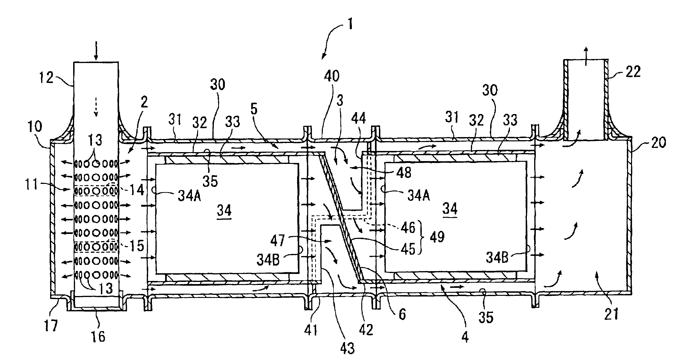
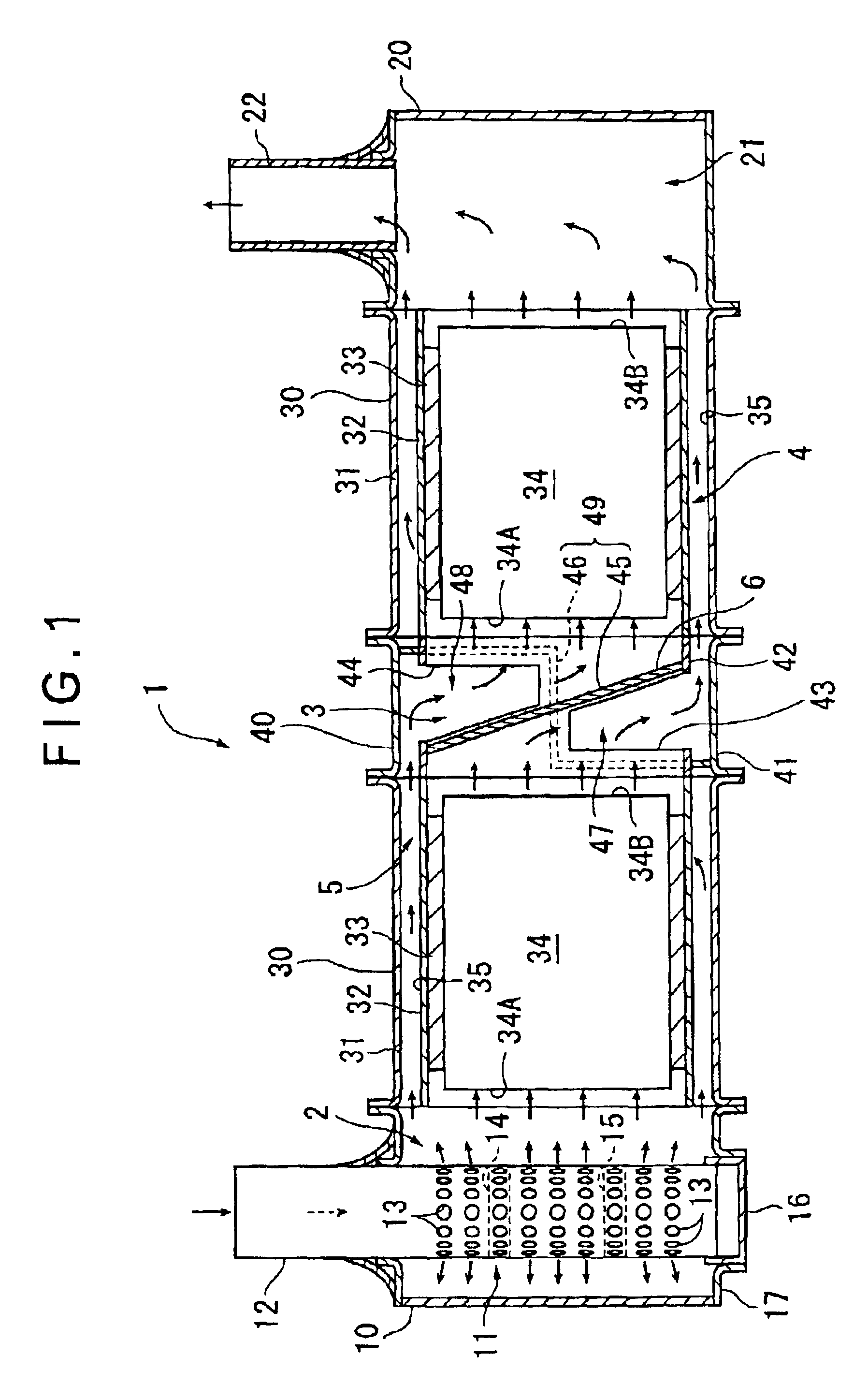
In FIG. 4, the exhaust gas purifying system 101 of this first modification differs from the above-described embodiment in that the internal wall 45 of the split flow unit 40 is not tilted and is arranged at right angles with the flow direction of the exhaust gas flowing in the carrier 34, and accordingly the developed shapes of the outlet-side opening portion 43 and the inlet-side opening portion 44 are rectangular. Other constructions are almost the same as those of the embodiment.

Such a modification can achieve the above-de...

second modification

[Second Modification]

FIG. 5 shows an exhaust gas purifying system 102 in accordance with a second modification of the present invention.

The exhaust gas purifying system 102 of the second modification has a construction such that a pair of carriers 34 are arranged in series in one carrier arrangement unit 30, and does not have the split flow unit 40 in the above-described embodiment.

Specifically, the carrier arrangement unit 30 has a large external cylindrical member 31 disposed between the inlet chamber unit 10 and the combined flow chamber unit 20. In this external cylindrical member 31, the upstream carrier 34 is arranged via the cushioning member 33.

In the center of the upstream-side carrier 34, a large through hole 342 is formed along the flow direction of exhaust gas. In this through hole 342, the upstream-side portion of a distribution flow path forming member 50 is inserted.

The distribution flow path forming member 50 includes a small-diameter cylindrical portion 51 inserted ...

third modification

[Third Modification]

FIG. 6 shows an exhaust gas purifying system 103 in accordance with a third modification of the present invention.

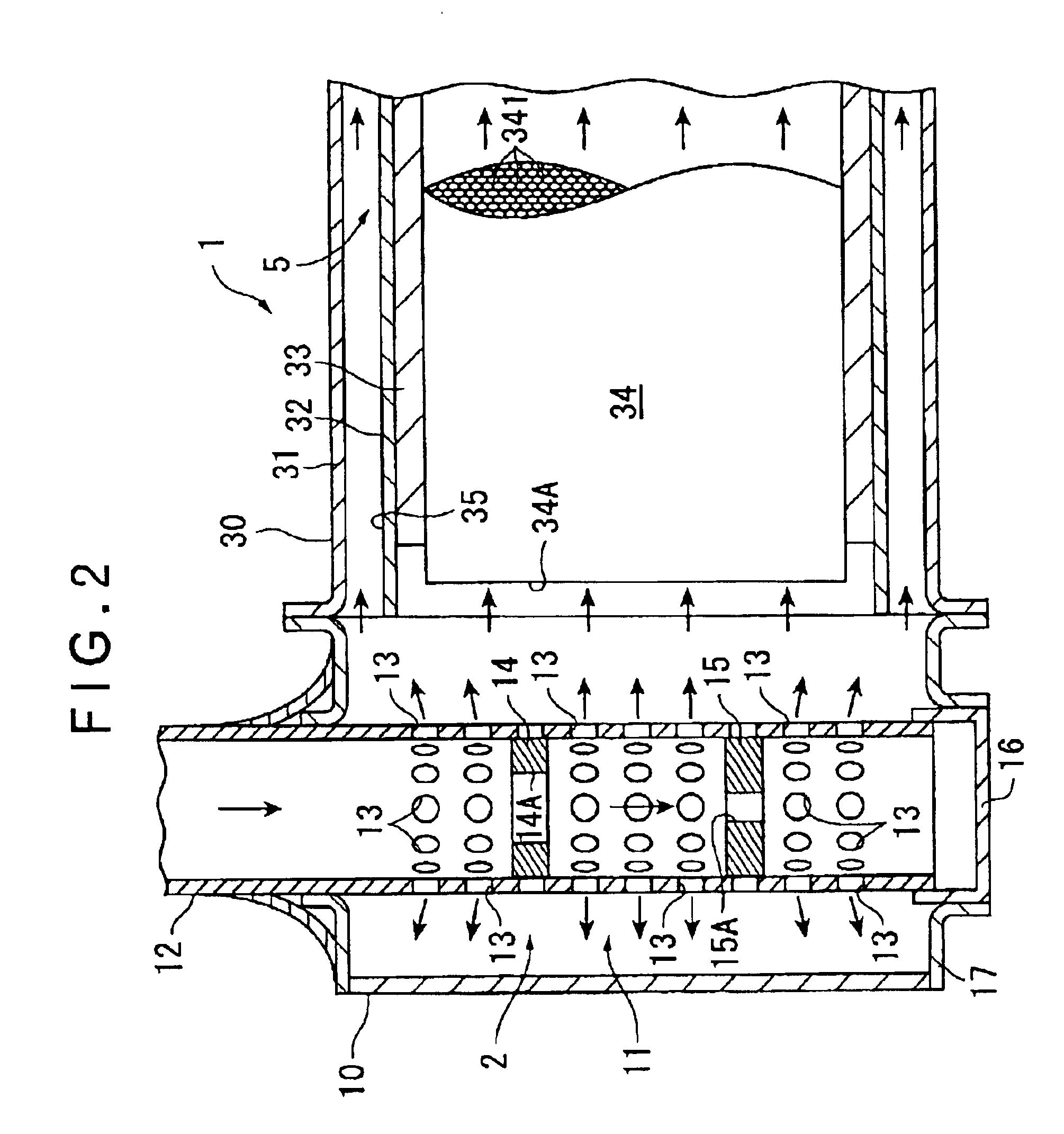
The exhaust gas purifying system 103 of this third modification differs from the above-described embodiment in that the inlet pipe 12 is installed in the direction along the flow direction of the exhaust gas flowing in the carrier 34, and that the flow straightening device 2 is formed by a flow straightening grating 60 having a plurality of holes 61. Other constructions are almost the same as those of the embodiment.

In this modification, the opening area of each of the holes 61 in the flow straightening grating 60 are small at positions close to the inlet pipe 12 and is larger as the distance from the inlet pipe 12 increases. Thereby, the flow distribution of the exhaust gas passing through the flow straightening grating 60 is improved. However, in the case where a sufficient flow straightening effect can be achieved even if the holes 61 having the sa...


PUM

PropertyMeasurementUnit
shapeaaaaaaaaaa
temperature distributionaaaaaaaaaa
thermal stressaaaaaaaaaa

Abstract

In an exhaust gas purifying system 1, a pair of carriers 34 is arranged in series along the flow direction of exhaust gas. Approximately a half of the exhaust gas passing through a first distribution flow path 4 flows in the upstream-side carrier 34, and the remaining half of the exhaust gas passing through a second distribution flow path 5 flows in the downstream-side carrier 34. Therefore, the capacity of the whole of the paired carriers 34 can be substantially doubled as in the case where the carriers 34 are arranged in parallel, so that the function as the exhaust gas purifying system 1 can be improved.

Description

1. Field of the InventionThe present invention relates to an exhaust gas purifying system for an internal combustion engine and, more particularly, to an exhaust gas purifying system provided in an exhaust passage of the internal combustion engine to purify exhaust gas.2. Description of Related ArtConventionally, it is known that an exhaust gas purifying system is provided in an exhaust passage of an internal combustion engine to collect particulates (particulate substances) in exhaust gas emitted from the internal combustion engine such as a diesel engine or to reduce NOx content.As an exhaust gas purifying system for collecting particulates, a system provided with an exhaust emission after-treatment device consisting of a diesel particulate filter (hereinafter referred to as a DPF) has been developed.As an exhaust gas purifying system for reducing NOx content, a system provided with an exhaust emission after-treatment device consisting of a NOx reduction catalyst (DeNOx catalyst) ...

Claims


Application Information

Patent Timeline
Patent Type & Authority Patents(United States)
IPC IPC(8): F01N3/28F01N3/08F01N7/18F01N7/00F01N7/04F01N3/02F01N3/021F01N3/022F01N3/023F01N3/031F01N3/035F01N3/18F01N3/20F01N3/24F01N13/04F01N13/18
CPCF01N3/0814F01N3/0842F01N3/2853F01N13/18F01N13/011F01N2470/02F01N2470/18Y10S55/30F01N13/017F01N3/021
Inventor NISHIYAMA, TOSHIHIKOWAKAMOTO, KOUTAROUEMORI, NOBUHIKO
Owner KOMATSU LTD
Why Eureka
Try Eureka