
Portable card unit processing apparatus

a processing apparatus and card unit technology, applied in the field of portable card unit processing apparatus, can solve the problems of considerable economic burden on the user, preparing both balance readers and ic cards r/w, and achieve the effect of small storage capacity of the storage section of the card uni

Inactive Publication Date: 2004-08-03
FUJITSU LTD
View PDF26 Cites 15 Cited by
  • Summary
  • Abstract
  • Description
  • Claims
  • Application Information

AI Technical Summary

Benefits of technology

Enables data transfer between the card unit and external apparatus, displays card data, and reduces the need for separate devices, saving space and cost, while ensuring operability by determining connection status automatically.

Problems solved by technology

However, preparing both of the balance reader and the IC card R / W is a considerable economical burden on the user.

Method used


Image

  • Portable card unit processing apparatus
  • Portable card unit processing apparatus
  • Portable card unit processing apparatus

Examples


first embodiment

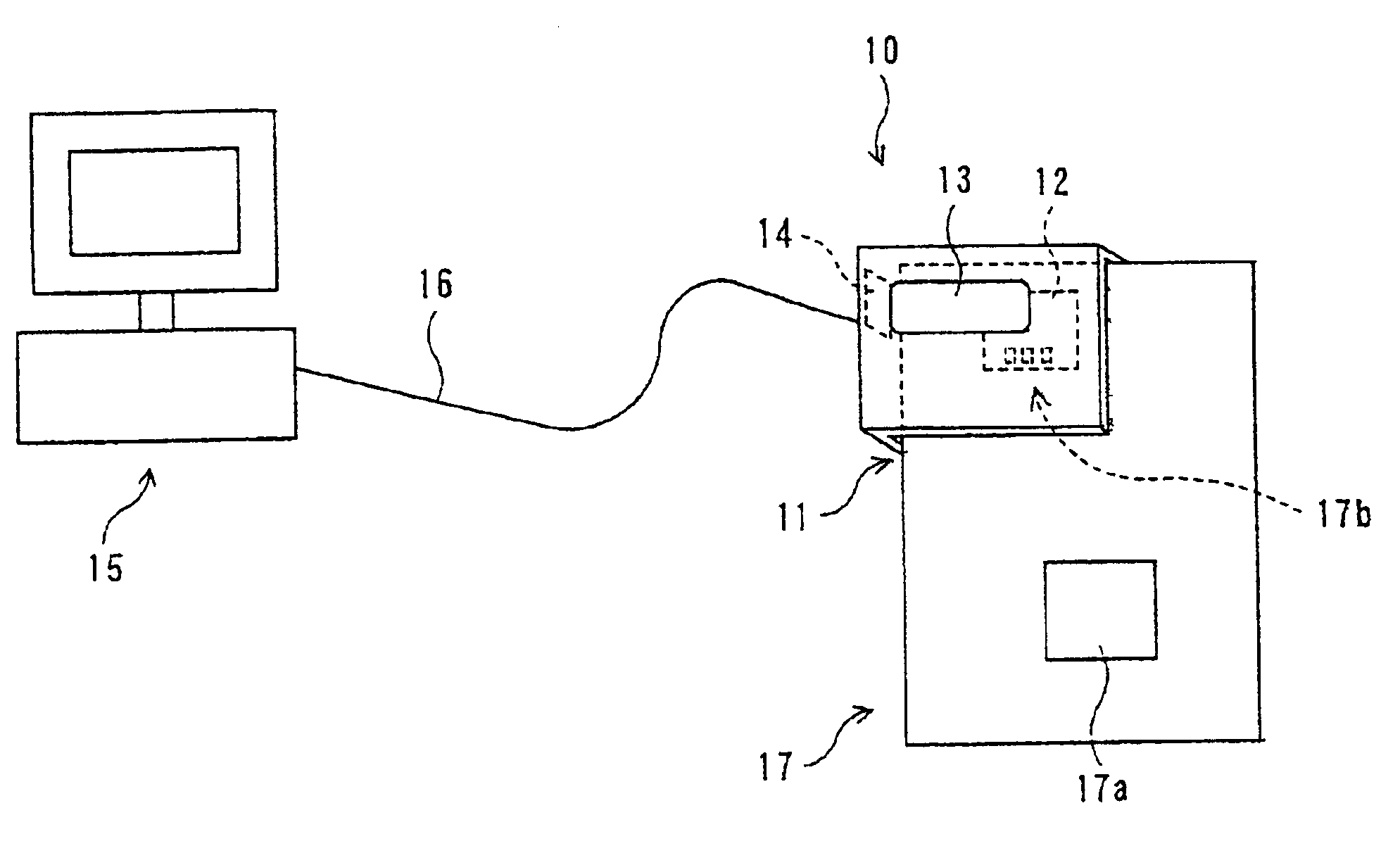
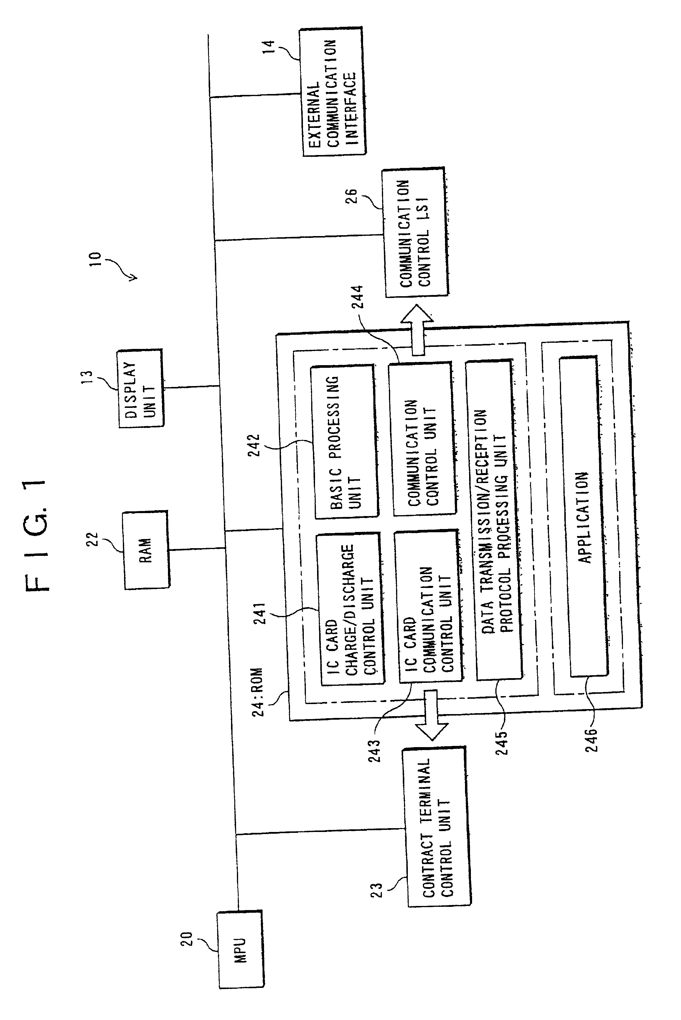
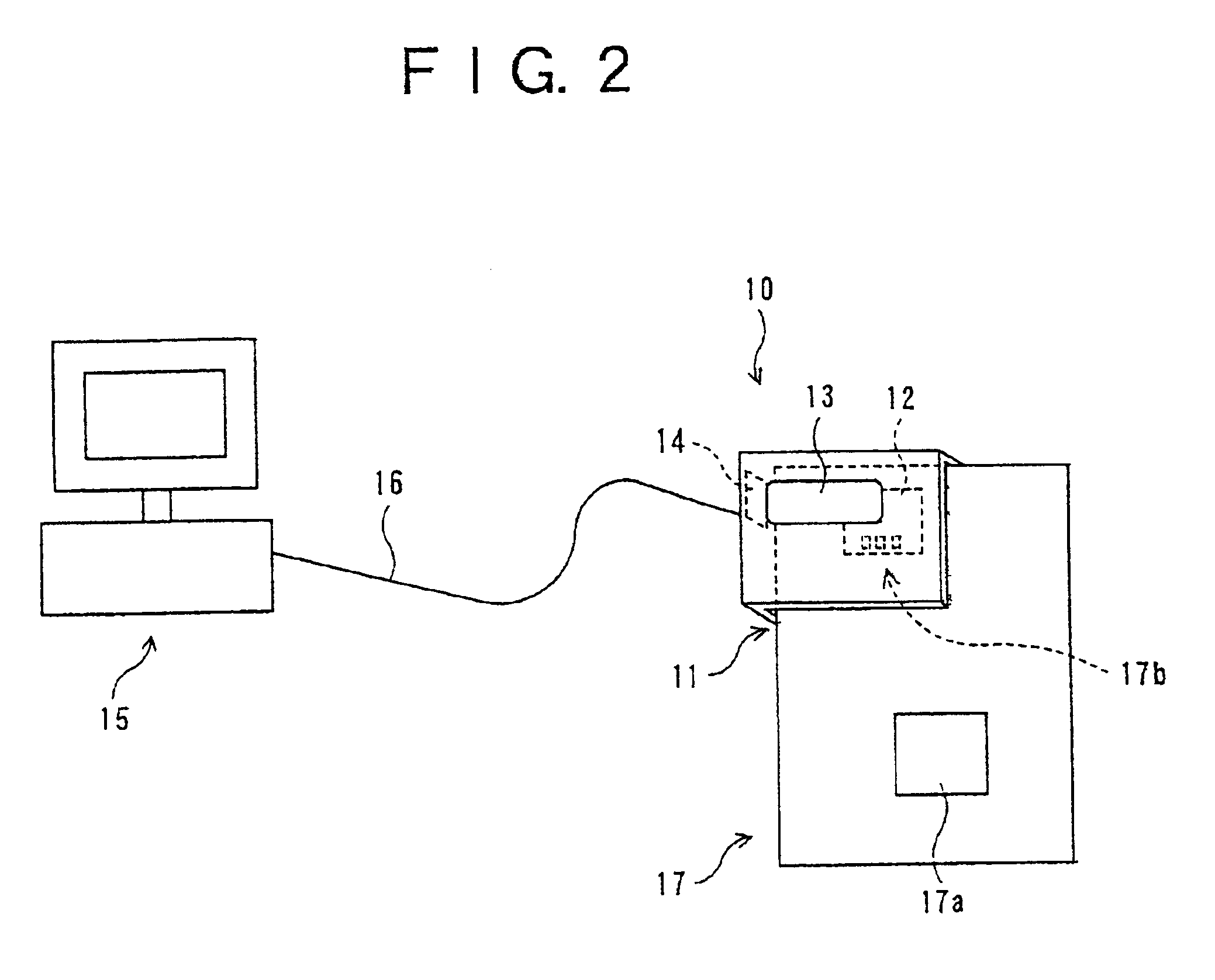
FIG. 1 is a block diagram showing a structure of an IC card processing apparatus (portable card unit processing apparatus) 10 according to this invention. FIG. 2 is a schematic diagram illustrating its structure.

Incidentally, the first embodiment will be described by way of example in which a card unit is an IC card used as a portable medium for electronic money defined as an electronic symbol of currency, and the present invention is applied to an IC card processing apparatus which processes data in the IC card.

Here, a memory (storage section) 17a is packaged in an IC card (card unit) 17 as shown in FIG. 2. In the memory 17a, there are stored a kind of electronic money, user information, use history and the like. The IC card 17 comprises a microprocessor not shown, which can control data transmission or process a cipher.

On the surface of the IC card 17 formed is a contact 17b to transmit / receive data between this apparatus 10 and an ATM of a bank, a POS terminal of a retail shop or...

second embodiment

(b) Description of Second Embodiment

FIG. 5 is a block diagram showing a hardware structure of an IC card processing apparatus (portable card unit processing apparatus) 10' according to a second embodiment of this invention. The IC card processing apparatus 10' shown in FIG. 5 is an IC card processing apparatus which processes an IC card (card unit) used as a portable medium for electronic money that is defined as an electronic symbol of currency, like the IC card processing apparatus 10 according to the first embodiment. The IC card processing apparatus 10' is attached thereto the IC card 17 to process it.

The portable card unit processing apparatus 10' according to the second embodiment of this invention comprises a non-volatile memory (save storage section) 30 in the portable card unit processing apparatus 10 according to the first embodiment shown in FIG. 1, and an ROM 24' instead of the ROM 24. Incidentally, like reference characters designate like or corresponding parts having b...


PUM


Abstract

The processing apparatus including a first communicating section (23, 243), a connecting unit (14) for being detachably connected to an external apparatus, a second communicating section (26, 244), a display section (13), and a control section (26, 244) so as to transfer data between the card unit and the external apparatus while the external apparatus is connected to the connecting section, (14), and controlling the first communicating section (23, 243) and the display section (13) so as to read data from the storage section of the card unit and to display the read-out data on the display section (13) while the external apparatus is disconnected from the concentrating section (14).

Description

The present invention relates to a portable card unit processing apparatus attached thereto a card unit having a storage unit to process the card unit, in particular, to a portable card unit processing apparatus being able to read / display various information (electronic money and the like) stored in the storage unit of the card unit.Electronic money systems which enable cashless commercial transactions are developed in recent years. An IC card in which an IC (Integrated Circuit) is integrated is used as a portable medium for electronic money. There is used a portable balance display (balance reader) in order that a possessor of the IC card refers to information (for example, a balance of electronic money) stored in a memory thereof.The balance reader comprises a card inserting opening, a contact and a display unit. The user inserts the IC card from the card inserting opening. Whereby, a contact of the IC card and the contact of the balance reader are electrically connected, and bala...

Claims


Application Information

Patent Timeline
Patent Type & Authority Patents(United States)
IPC IPC(8): G07F7/00G06K19/077G07F7/08G06K17/00
CPCG06K17/0022G06K19/077G06K19/07741G07F17/0014
Inventor ONO, AKIKOHASHIMOTO, SHIGERU
Owner FUJITSU LTD
Learn More