3R optical signal regeneration

a technology of optical signal and regeneration solution, applied in the direction of logic circuits, instruments, pulse techniques, etc., can solve the problems of not being able to achieve good decision window characteristics with a single interferometer, the capacity of the signal obtained to resist line distortion is not good enough for direct use as a transmitter, and the reconstitution solution is not necessarily the most practical or the most effective for subsequent timing insertion

Inactive Publication Date: 2004-08-10
RPX CORP
View PDF5 Cites 16 Cited by
  • Summary
  • Abstract
  • Description
  • Claims
  • Application Information

AI Technical Summary

Problems solved by technology

The use of interferometers the arms of which comprise semi-conductor optical amplifiers, whether in phase or in anti-phase, does not make it possible to obtain good decision window characteristics with a single interferometer.
The capacities of the signal obtained to resist line distortions are not good enough for direct use as a transmitter.
Moreover, these reconstitution solutions are not necessarily the most p

Method used


Image

  • 3R optical signal regeneration
  • 3R optical signal regeneration
  • 3R optical signal regeneration

Examples


first embodiment

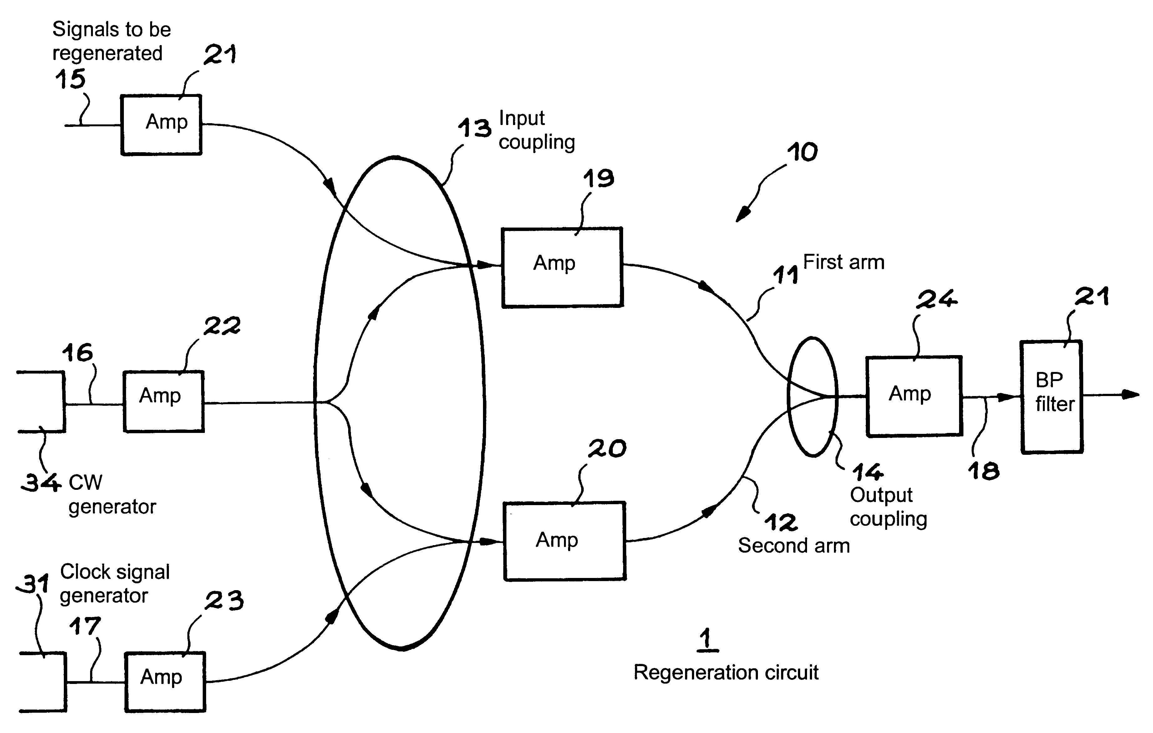
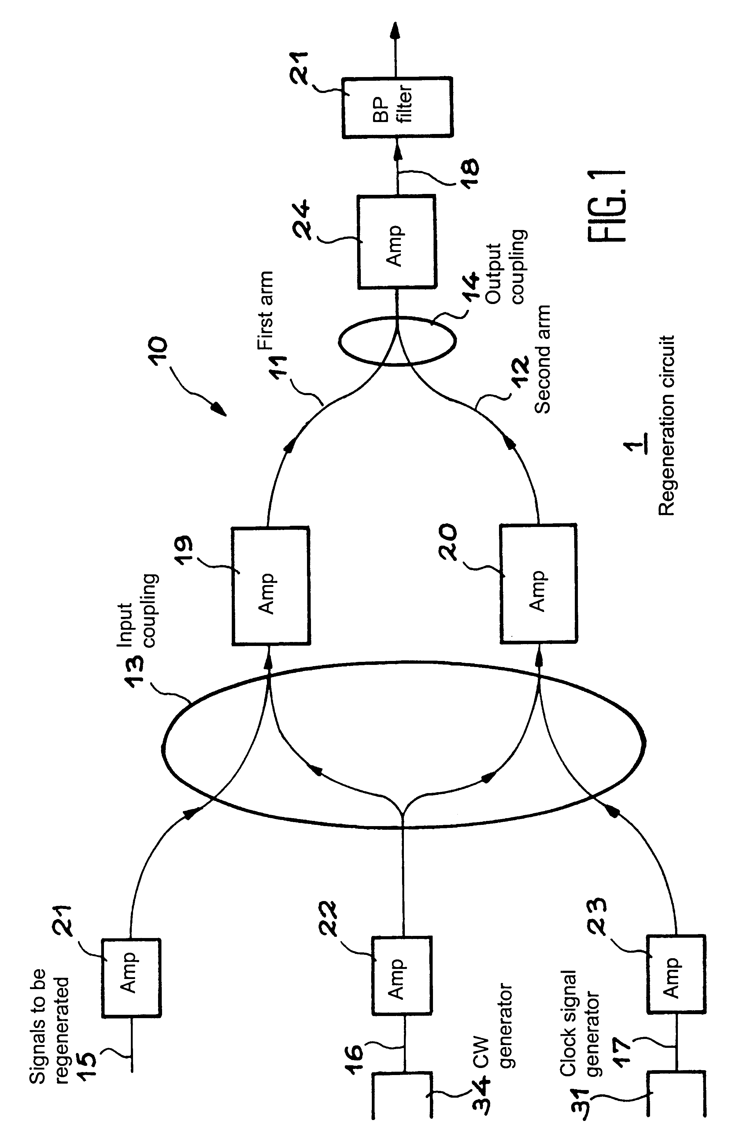
Comments will now be given on the invention in relation to FIG. 1.

The regeneration circuit 1 includes an interferometric structure 10, for example a Mach-Zehnder, including a first arm 11 and a second arm 12. Input coupling means 13 couple the first arm 11 to guides, for example, optical fibers 15 and 16. The coupling means 13 couple the second arm 12 to the guide 16 on the one hand, and to a guide 17, for example, an optical fiber.

Output coupling means 14 couple each of the arms 11, 12 to an output guide 18.

Each of the arms 11, 12 comprises a semi-conductor optical amplifier, 19, 20, respectively. The output guide 18 feeds a bandpass filter 21 the output of which constitutes the output of the device 1 according to the invention.

The arm 16 is coupled to a continuous wave generator 34, and the arm 17 to a clock signal generator of the signal to be regenerated, preferably a recoverer of such a signal.

Optionally, each of the input guides 15-17 and the output guide 18 may include optica...


PUM


Abstract

An optical signal regeneration device having an interferometric structure with two arms. Each of the arms has a medium, the optical power output of which is variable with the optical power input. The first arm receives, through an input coupler, a continuous wave and the signal to be regenerated. The second arm receives through the input coupler, a continuous wave signal and a clock signal. A filter, centered on the continuous wave wavelength, receives the output signal of the interferometric structure through the coupler. The filter output signal constitutes the regenerated 3R signal.

Description

The invention is located in the field of data transfer optical signal regeneration circuits. It is applicable to transmissions the code of which is or is not with return to zero.PRIOR ARTThe technique is known of using interferometers the arms of which comprise semi-conductor optical amplifiers to make decision windows. These interferometers which use a continuous wave source constituting the output carrier wave may be used in an anti-phase (out of phase) or an in-phase configuration.When they are used in anti-phase, good non linearity and therefore good reshaping is obtained. However, in this case, the capacity of the converted wave to withstand the signal pulse distortions brought by the line (good chirp qualities) is reduced, when standard fiber is used.When they are used in phase the capacity of the converted signal to resist signal pulse distortions is improved, but the non linearity is reduced.An interferometer, the arms of which comprise semi-conductor optical amplifiers, may...

Claims


Application Information

Patent Timeline
IPC IPC(8): H04B10/17G02F2/02G02F3/00H01S5/50H04B10/291H04B10/299
CPCH04B10/2914H04B10/299
Inventor JANZ, CHRISTOPHERGUERBER, PATRICIALAVIGNE, BRUNOWOLFSON, DAVIDFJELDE, TINAKLOCH, ALLAN
Owner RPX CORP
Why Eureka
Try Eureka