Method of positioning cells for electrophysiological testing

Inactive Publication Date: 2004-08-17
MOLECULAR DEVICES
View PDF6 Cites 42 Cited by
  • Summary
  • Abstract
  • Description
  • Claims
  • Application Information

AI Technical Summary

Benefits of technology

Therefore, according to these and other objectives, the present invention consists of a perfusion-chamber structure that includes a chamber plate with an extracellular compartment, a partition plate with an electrode aperture, and a foundation plate with an intracellular compartment. A gap between the chamber plate and the partition plate produces a channel for applying suction that draws extracellular solution from the extracellular compartment and facilitates the movement and positioning of a test cell over the electrode aperture. According to a very important aspect of the invention, the suction portion of the positioning procedure for the test cell is accompanied by a slight positive pressure applied to the intracellular solution in the intracellular compartment of the chamber to cause upward flow of the intracellular solution

Problems solved by technology

Thus, any leakage of current through the seal is undesirable and the creation of a high-resistance seal (in the order of giga-ohms) is crucial for good results.
When such mixing occurs, the homogeneity of the intracellular solution is reduced and its fun

Method used


Image

  • Method of positioning cells for electrophysiological testing
  • Method of positioning cells for electrophysiological testing
  • Method of positioning cells for electrophysiological testing

Examples


Embodiment Construction

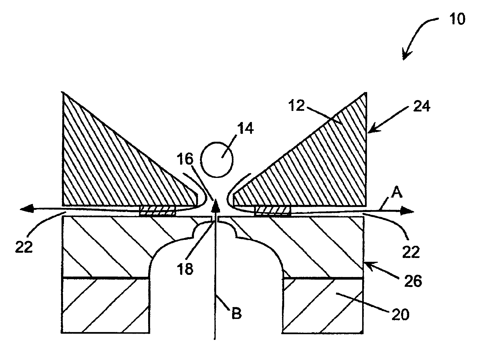
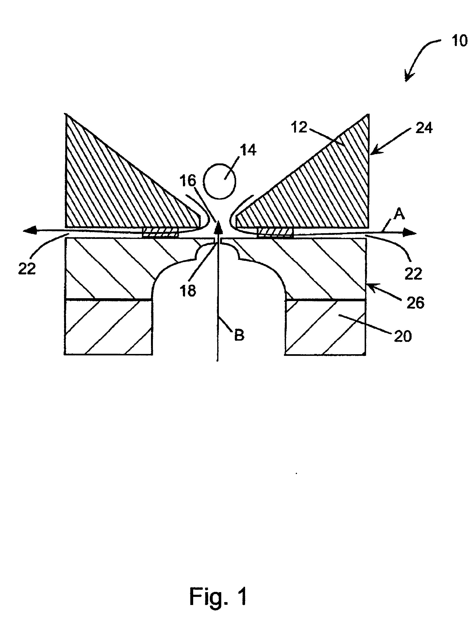
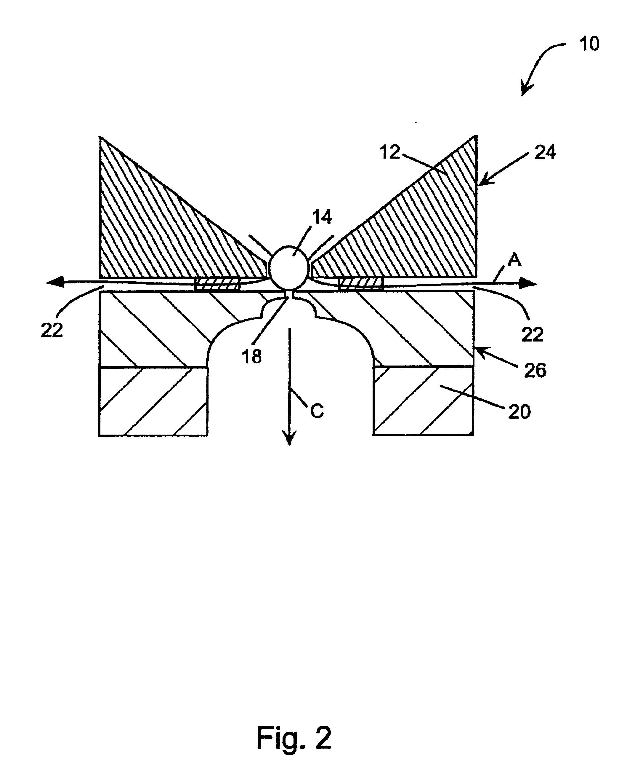
A major aspect of this invention lies in the procedure used to draw a biological membrane toward an electrode aperture to form a seal in a perfusion chamber for electrophysiological recording. A pressure (positive or negative) is applied to the extracellular fluid in the extracellular compartment of the chamber to cause flow of the biological membrane being tested toward the electrode aperture. At the same time, sufficient positive pressure is applied to the intracellular fluid in the intracellular compartment to either cause flow of intracellular fluid into the extracellular compartment through the electrode aperture or at least prevent flow of extracellular fluid into the intracellular compartment. When the biological membrane approaches the electrode aperture in the extracellular compartment, suction is applied to the aperture from the intracellular compartment to draw the membrane in and form a seal. The initial countercurrent flows of fluids near the electrode aperture in the e...


PUM

PropertyMeasurementUnit
Pressureaaaaaaaaaa
Flow rateaaaaaaaaaa
Electrical resistanceaaaaaaaaaa

Abstract

A perfusion-chamber structure includes a chamber plate with an extracellular compartment, a partition plate with an electrode aperture, and a foundation plate with an intracellular compartment. A gap between the chamber plate and the partition plate produces a channel for applying suction that draws extracellular solution from the extracellular compartment and facilitates the movement and positioning of a test cell over the electrode aperture. The positioning procedure for the test cell is accompanied by a slight positive pressure applied to the intracellular solution in the intracellular compartment of the perfusion chamber to cause upward fluid flow through the electrode aperture. When the cell is positioned over the electrode aperture, the positive pressure on the intracellular fluid is reversed to suction and the cell is seated thereby to form the seal.

Description

1. Field of the InventionThis invention is related in general to electrodes for electrophysiological testing of biological membranes. In particular, the invention concerns the manufacture of an electrode assembly suitable for massive parallel electrophysiological testing of cells, and a method for rapidly and reliably positioning the cells in each chamber for forming a high electrical-resistance patch clamp.2. Description of the Related ArtIn conventional voltage-clamping techniques used to conduct electrophysiological tests on a membrane, the electrical activity in the membrane is assessed by measuring current or voltage changes produced in response to exposure to various test stimuli. Typically, the membrane is pierced with two microelectrodes connected to an amplifier capable of recording current or voltage variations in response to stimuli such as voltage step changes, current injection, the application of compounds, or mechanical stimulation.Similarly, using patch-clamping tech...

Claims


Application Information

Patent Timeline
IPC IPC(8): C12M1/34G01N33/487
CPCG01N33/48728
Inventor OSIPCHUK, YURI
Owner MOLECULAR DEVICES
Why Eureka
Try Eureka