Glass composition, sealing glass for magnetic head and magnetic head using the same

a technology of sealing glass and glass composition, which is applied in the direction of manufacturing head surfaces, instruments, record information storage, etc., can solve the problems of eroding the sealing glass, affecting the effect of the sealing glass, and increasing the requirements for the glass materials used in the purpose discussed abov

Inactive Publication Date: 2004-08-17
PANASONIC CORP
View PDF12 Cites 12 Cited by
  • Summary
  • Abstract
  • Description
  • Claims
  • Application Information

AI Technical Summary

Benefits of technology

In order to obtain a lead-free glass material having a low softening point, it is necessary to use a component having the function of lowering the softening point and working temperature, in place of an oxide of lead. The present invention provides a glass composition mainly composed of an oxide of bismuth, which has a working temperature of from 450.degree. C. to 650.degree. C., a coefficient of thermal expansion of from 70.times.10.sup.-7 to 130.times.10.sup.-7 / .degree. C. and an excellent water resistance.
Although Al.sub.2 O.sub.3 is not necessarily an essential component, it has the functions of accelerating vitrification and improving water resistance. However, when its content is more than 4 wt %, the working temperature exceeds 650.degree. C.; therefore, the content is preferably from 0 to 4 wt %.

Problems solved by technology

In recent years, with the increasing demand for the realization of high performance and high reliability for electronic equipment and various parts, including the above-described magnetic heads, the requirements for the glass materials used in the purpose discussed above have become more severe.
However, the conventionally used glasses having a low softening point including lead glasses are not sufficient, especially in terms of water resistance, to be used for the recent electronic equipment and various parts each having even higher performance and higher reliability.
In particular, with the increasing demand for the realization of higher performance and higher reliability, a magnetic head is occasionally exposed to a grinding fluid or the like for a long time during the processing step, resulting in a problem of eroding the sealing glass.
In other words, the chemical durability of the sealing glass has often posed problems.

Method used


Image

  • Glass composition, sealing glass for magnetic head and magnetic head using the same
  • Glass composition, sealing glass for magnetic head and magnetic head using the same
  • Glass composition, sealing glass for magnetic head and magnetic head using the same

Examples


example 31

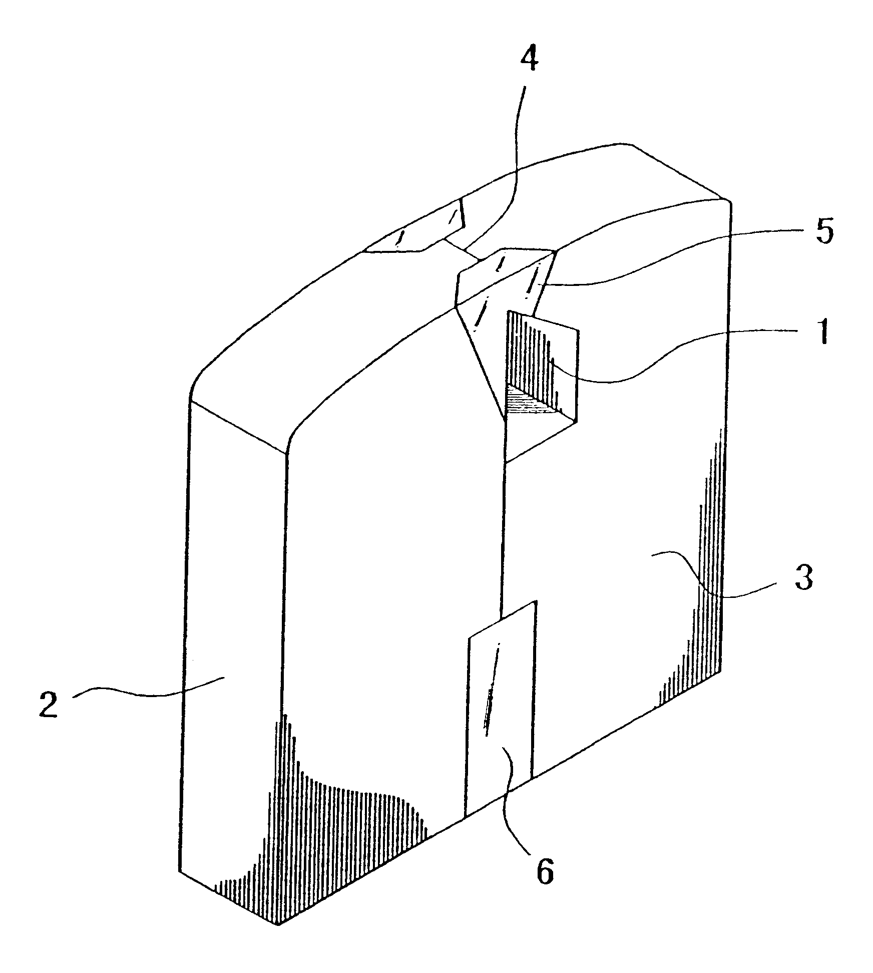
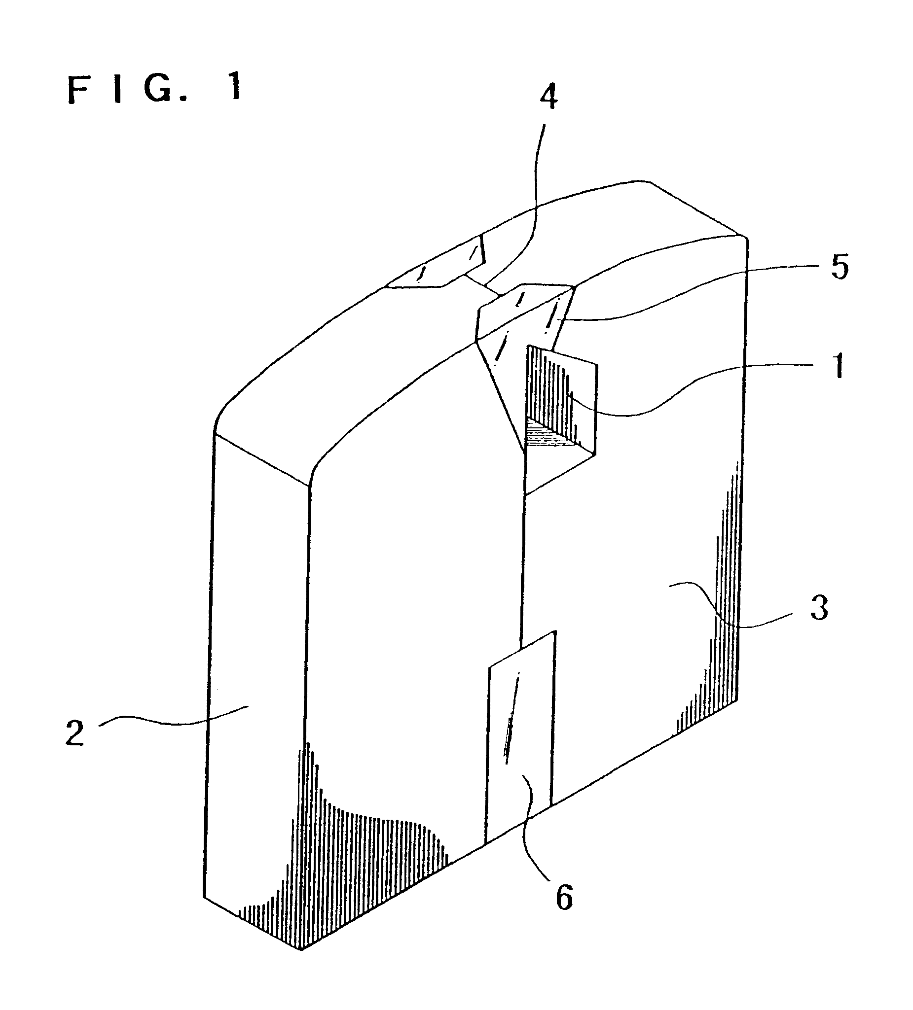
FIG. 1 shows a perspective view of a ferrite head as one example of a magnetic head in accordance with the present invention. A magnetic core half 2 comprising ferrite and a magnetic core half 3 comprising ferrite that was provided with a groove 1 for a coil were butted against each other with a magnetic gap material 4 interposed therebetween, and bonded together with sealing glasses 5 and 6.

The glass composition 8 produced in the above example was used as the sealing glasses 5 and 6, each of which was heat-treated at 605.degree. C. to complete the fabrication of the ferrite head shown in FIG. 1.

Mn--Zn single crystal ferrite was used as the ferrite constituting the magnetic core halves 2 and 3, and fused silica was used as the magnetic gap material 4.

The fabricated ferrite head produced no crack or fracture, and no erosion or the like was observed in the sealing glass portion, thereby exhibiting a desired magnetic transducing characteristic.

example 32

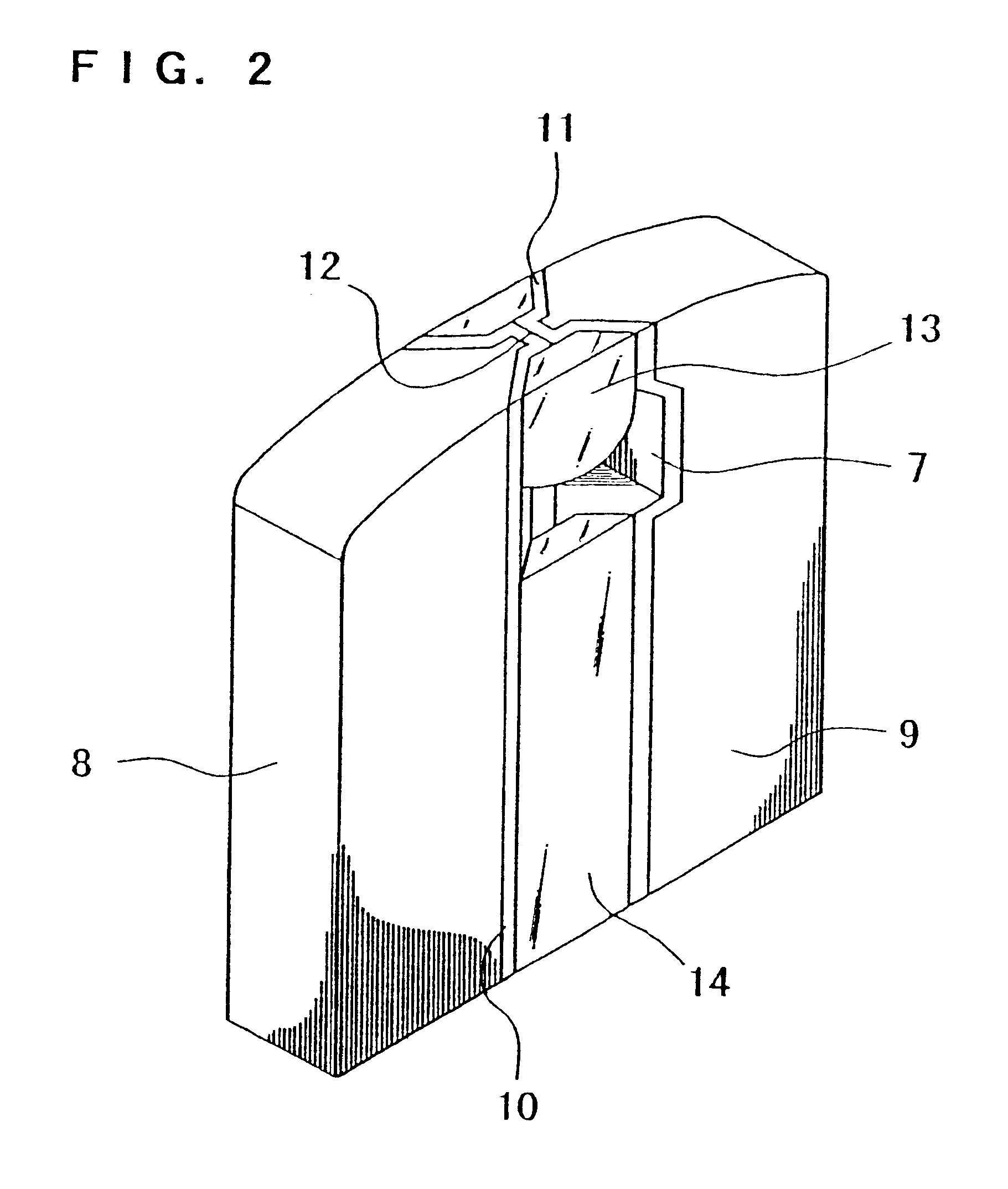
FIG. 2 shows a perspective view of an MIG head as one example of a magnetic head in accordance with the present invention. At magnetic gap-facing surfaces of magnetic core halves 8 and 9, each of which comprised ferrite and was provided with a groove for a coil 7, magnetic metal films 10 and 11 were provided to form a magnetic gap material 12 between the magnetic metal films 10 and 11. The magnetic core halves 8 and 9 were bonded together with sealing glasses 13 and 14.

The glass composition 18 of the above example was used as the sealing glasses 13 and 14, each of which was heat-treated at 515.degree. C. to complete the fabrication of the MIG head shown in FIG. 2. Mn--Zn single crystal ferrite was used as the ferrite constituting the magnetic core halves 8 and 9 a film of Fe--Ta--N having a saturation magnetic flux density (Bs) of 1.6 T was used as the magnetic metal films 10 and 11, and fused silica was used as the magnetic gap material 12.

The fabricated MIG head produced no crack ...

example 33

FIGS. 3 and 4 show an example of a laminated head as one example of a magnetic head in accordance with the present invention. FIG. 3 is a perspective view of another example of a magnetic head in accordance with the present invention. FIG. 4 is a top plan view of a relevant part of the magnetic head shown in FIG. 3.

A magnetic core half 21, which was provided with a groove 15 for a coil and constituted by sandwiching a laminated body of a magnetic metal film 16 and an insulating film 17 between non-magnetic substrates 18 and 19, and a magnetic core half 20, which was constituted by sandwiching the same laminated body as above between non-magnetic substrates, were butted against each other with a magnetic gap material 22 interposed therebetween, and bonded together with sealing glasses 23, 24 and 25.

The glass composition 9 of the above example was used as the sealing glasses 23, 24 and 25, each of which was heat-treated at 495.degree. C. to complete the fabrication of the laminated he...


PUM

PropertyMeasurementUnit
viscosityaaaaaaaaaa
viscosityaaaaaaaaaa
temperatureaaaaaaaaaa

Abstract

In order to provide a practically lead-free glass composition having a low softening point and an excellent water resistance for use in various parts of electronic equipment and a magnetic head using the same, a glass composition is provided, which contains 0.5 to 14 wt % of SiO2, 3 to 15 wt % of B2O3, 4 to 22 wt % of ZnO, 55 to 90 wt % of Bi2O3, 0 to 4 wt % of Al2O3, 0 to 5 wt % of at least one selected from the group consisting of Li2O, Na2O and K2O, and 0 to 15 wt % of at least one selected from the group consisting of MgO, CaO, SrO and BaO.

Description

The present invention relates to a glass composition having a low softening point which is used as a bonding material, sealing material, coating material for materials such as ceramics, glass and metal, or as a paste material and the like.The present invention also relates to a magnetic head suitable for recording and reproducing magnetic information on a magnetic recording medium, and to a sealing glass for bonding a pair of magnetic core halves constituting such a magnetic head.In various parts used for electronic equipment, different glass materials are used as the materials for bonding, sealing or coating a variety of components each comprising ceramics, glass, metal or the like. These materials are used in various forms such as a bulk, powder, fiber and thin film, either as a material consisting only of glass or as a composite material comprising a glass material and other materials. Also used in a variety of applications is a paste material imparted various functions, which is...

Claims


Application Information

Patent Timeline
Patent Type & Authority Patents(United States)
IPC IPC(8): C03C8/04C03C3/066C03C8/24C03C3/062C03C8/00G11B5/127G11B5/133G11B5/187G11B5/193
CPCC03C3/066C03C8/04C03C8/24G11B5/1272G11B5/1335G11B5/1878G11B5/193
Inventor HASEGAWA, SHINYAKANAI, MIKIETORII, HIDEOKAMIMOTO, TETSUYA
Owner PANASONIC CORP
Why Eureka
Try Eureka