Cleat-forming woven fabric article for the manufacture of anti-creep floor mats

a technology of woven fabric and floor mats, which is applied in the direction of carpet fasteners, carpet cleaners, instruments, etc., can solve the problems of cleats being quickly worn away, unwanted and potentially floor staining or dirtying articles needing to be removed, and attempts to use foam rubber backings on cleated floor mats or carpets. , to achieve the effect of easy and efficient production

Inactive Publication Date: 2004-09-07
MILLIKEN & CO
View PDF25 Cites 17 Cited by
  • Summary
  • Abstract
  • Description
  • Claims
  • Application Information

AI Technical Summary

Benefits of technology

In view of the foregoing, it is a general object of the present invention to provide an in-line method for the production of cleats in a rubber or rubber-backed floor mat. Furthermore, it is an object of this invention to provide a novel conveyor belt system for an in-line floor mat manufacturing apparatus. Additionally, an object of this invention is to provide a cleated anti-creep floor mat which is more easily and efficiently produced than standard cleated floor mats. Still another object of this invention is to provide an anti-creep floor mat which exhibits not only cleats to provide anti-slip characteristics, but also intermittent patterned areas within the rubber on the underside of the rubber floor mat component which mirrors the woven structure of the perforated fabric article. Another object of the present invention is to provide a foam rubber floor mat having a relatively thin skin of dense rubber on an outer layer thereof, and further having cleats that include a thick skin of dense rubber on at least the bottom portions of the cleats. Yet another object of the present invention is to provide a foam rubber floor mat as described above, which further includes a carpet pile secured to one side thereof.

Problems solved by technology

Moisture, dirt, and debris from out of doors easily adhere to such footwear, particularly in inclement weather and particularly in areas of grass or mud or the like.
Such unwanted and potentially floor staining or dirtying articles need to be removed from a person's footwear prior to entry indoors.
Such cleats are formed during a vulcanization step and have required a time-consuming procedure of placing the green (unvulcanized) rubber sheet on a molded, perforated silicone pad which is itself placed by hand on the conveyor belt of a dust control manufacturing apparatus.
Heretofore, attempts to use a foam rubber backing on cleated floor mats or carpets have been mostly unsuccessful because the foam rubber is rather weak, with poor abrasion resistance, which leads to the cleats being quickly worn away.
The foam rubber is too soft to withstand the daily rigors of wear and tear in combination with the periodic laundering process.
Such a procedure is labor-intensive and inefficient.
However, until now, there have been no disclosures of proper methods to reduce the time and labor required to effectively and efficiently produce rubber-backed cleated floor mats.
However, there has been no discussion or suggestion regarding the problems associated with cleat-forming perforated conveyor belts in the past.

Method used


Image

  • Cleat-forming woven fabric article for the manufacture of anti-creep floor mats
  • Cleat-forming woven fabric article for the manufacture of anti-creep floor mats

Examples


Embodiment Construction

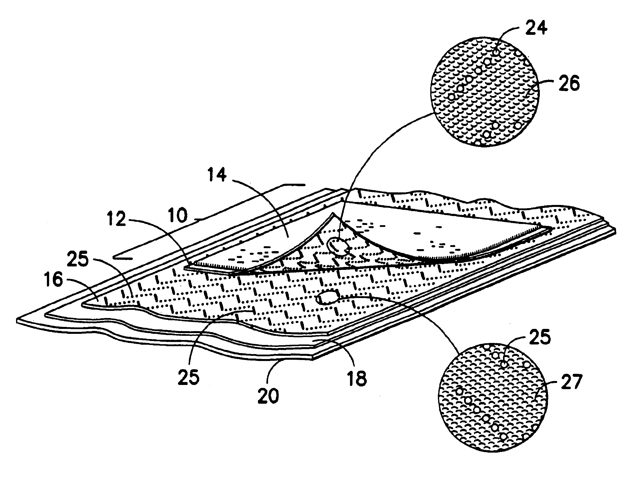
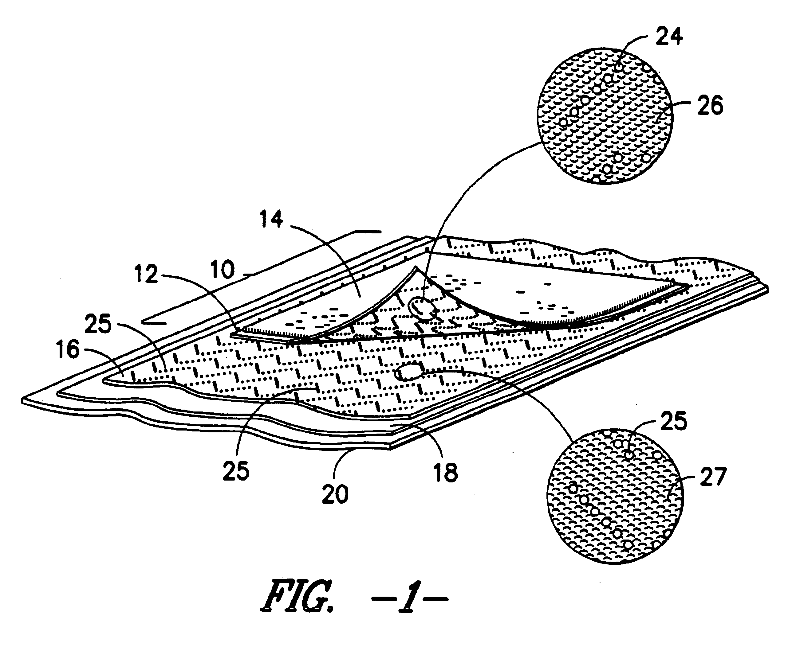
solid rubber mat having the dense, solid rubber cleats was tested and compared to a foam rubber mat manufactured in accordance with the instant method. The units shown are millimeters of mat movement after a series of 100 two-step passes.

Surface Solid Rubber Mat with Cleats Foam Rubber Mat with Cleats

The test is performed by placing a test mat, which measures 85 centimeters .times.150 centimeters, on the surface to be tested. The position of the mat is marked and the mat is walked over 100 times, in the same direction, with each pass placing both feet on the mat (two steps). As the test is performed on a comparative basis to a control sample (in the present case the solid rubber mat) the person or people walking on the mat can vary from test to test, however it was an adult of average weight (75-90 kilograms) wearing normal outdoor shoes. The movement is measured after the 100 passes. Thus, the above test provides results based on comparative testing.

It can be seen from the results ...


PUM

PropertyMeasurementUnit
thickaaaaaaaaaa
temperatureaaaaaaaaaa
pressureaaaaaaaaaa

Abstract

The present invention relates to specific methods of producing cleated rubber-backed floor mats (such as dust control or rubber mats) through the utilization of the combination of a perforated coated woven fabric article and a cushioned platen liner between the article and the metal platen of an in-line dust control mat manufacturing machine. Such a procedure permits a more efficient manner of producing cleated anti-creep dust control mats than previously followed. In particular, the fabric article is in the form of a conveyor belt and is preferably constructed from Teflon(R)-coated woven fiberglass which will not adhere to the tacky rubber component of the target mat and can withstand the extremely high vulcanization temperatures and pressures required during the production of a dust control mat. The cushioned platen liner, which is preferably comprised of or coated with silicon, is utilized as a separator between the metal platen of the manufacturing machine, as well as cushion for the molten rubber as it is pressed through the conveyor belt perforations during vulcanization. Such a cushioned liner material substantially eliminates any problems due to the force of the metal platen against the molten rubber as it passes through the article perforations. Further, a method for utilizing the conveyor belt to produce foam rubber cleated anti-creep mats is disclosed. The cleats of these mats have a thicker skin than the rest of the mat, thereby imparting enough strength and structural integrity so that the foam rubber mats may withstand the daily rigors of use, combined with periodic launderings. The produced mat as well as the woven fabric article/cushioned platen liner combination are also encompassed within this invention.

Description

The present invention relates to specific methods of producing cleated rubber-backed floor mats (such as dust control or rubber mats) through the utilization of the combination of a perforated coated woven fabric article and a cushioned platen liner between the article and the metal platen of an in-line dust control mat manufacturing machine. Such a procedure permits a more efficient manner of producing cleated anti-creep dust control mats than previously followed. In particular, the fabric article is in the form of a conveyor belt and is preferably constructed from Teflon.RTM.-coated woven fiberglass which will not adhere to the tacky rubber component of the target mat and can withstand the extremely high vulcanization temperatures and pressures required during the production of a dust control mat. The cushioned platen liner, which is preferably comprised of or coated with silicon, is utilized as a separator between the metal platen of the manufacturing machine, as well as cushion ...

Claims


Application Information

Patent Timeline
Patent Type & Authority Patents(United States)
IPC IPC(8): A47G27/04A47G27/00A47L23/26A47L23/00B32B25/10B32B25/00
CPCA47L23/266A47G27/0412B32B25/10Y10T428/24182Y10T428/24331Y10T428/2457Y10T428/24355Y10T428/24512Y10T428/1362Y10T428/163Y10T428/24504Y10T428/24033Y10T428/24562Y10T428/24479Y10T428/24496Y10T428/164Y10T428/23907Y10T428/23914Y10T428/23929Y10T428/23943Y10T428/2395Y10T428/23979Y10T428/23986Y10T428/249989A47G27/02B32B5/024B32B2305/026B32B2327/18B32B2471/04
Inventor BURKE, III, WILLIAM O.KERR, ROBERT C.LANG, AAGE
Owner MILLIKEN & CO
Why Eureka
Try Eureka