Transmission for wind generators

a technology for wind generators and transmission lines, applied in the direction of electric generator control, machine/engine, gearing, etc., can solve the problem of large overall length

Inactive Publication Date: 2004-09-14
RENK AG
View PDF17 Cites 46 Cited by
  • Summary
  • Abstract
  • Description
  • Claims
  • Application Information

AI Technical Summary

Benefits of technology

Thanks to the advantageous conical shape of the rotor (10), the diameter of which increases towards the rotor head (11), a high bearing capacity is obtained at the outer bearing (9) through the large bearing diameter. By virtue of the arrangement of the rotor (10), the bearing arrangement (9) can be placed right at the outside, in the transmission cover (8, 8'), resulting in a large span between the rotor bearings (9, 15). This span can be lengthened without any effort in terms of design merely by making the rotor (10) and the housing (3) wider.
Both bearings (9, 15) are embodied as hydrostatic sliding-contact bearings, which can be supplied with oil by a pump (30) and thus have hydrostatic start-up properties. To start up the system, the bearings (9, 15) are raised hydrostatically by operating the electric pump with power from the network connected. As the speed of the rotor (10) increases, the oil pump can be controlled by means of a control and regulating unit (32) and the oil delivery pressure can be deliberately reduced or switched off. This enables the bearings (9, 15) to be supplied selectively on an individual basis with the required quantity of lubricating oil or the required oil pressure. It is thus possible to establish operating conditions in which the oil pressure in the lubricating gap is built up in part hydrodynamically and in part hydrostatically or in a purely hydrodynamic manner.

Problems solved by technology

Such plants are assembled from a large number of components in an involved process and result in a large overall length.

Method used


Image

  • Transmission for wind generators
  • Transmission for wind generators
  • Transmission for wind generators

Examples


Embodiment Construction

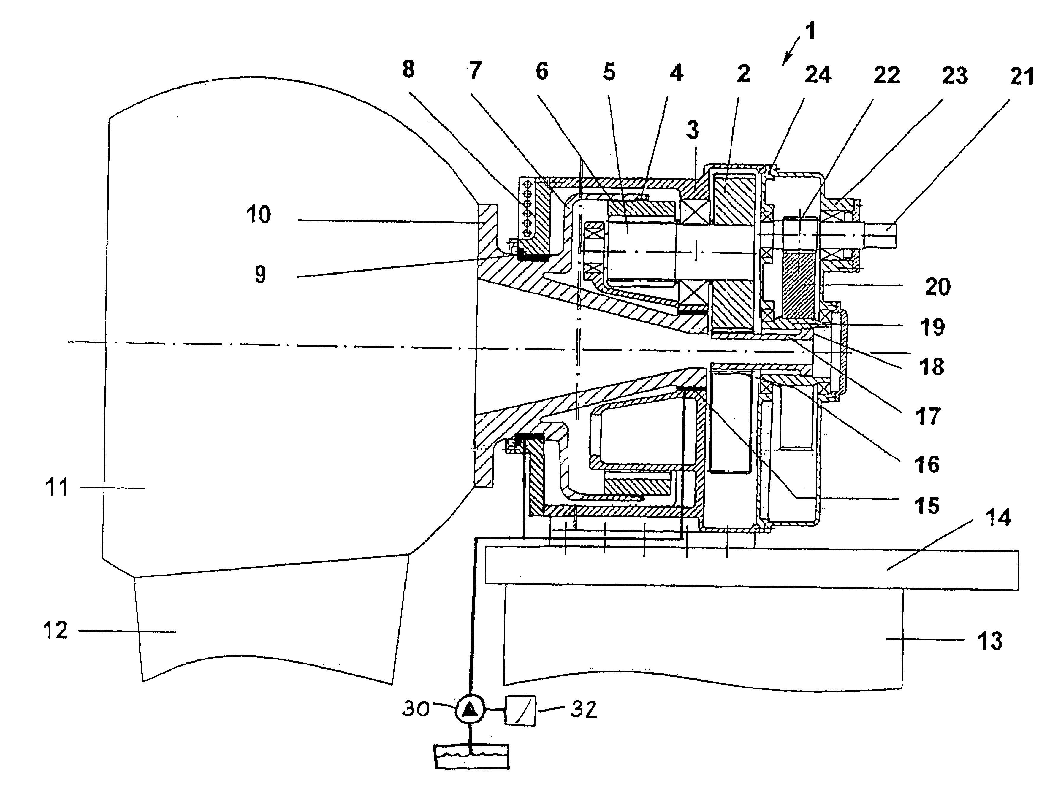
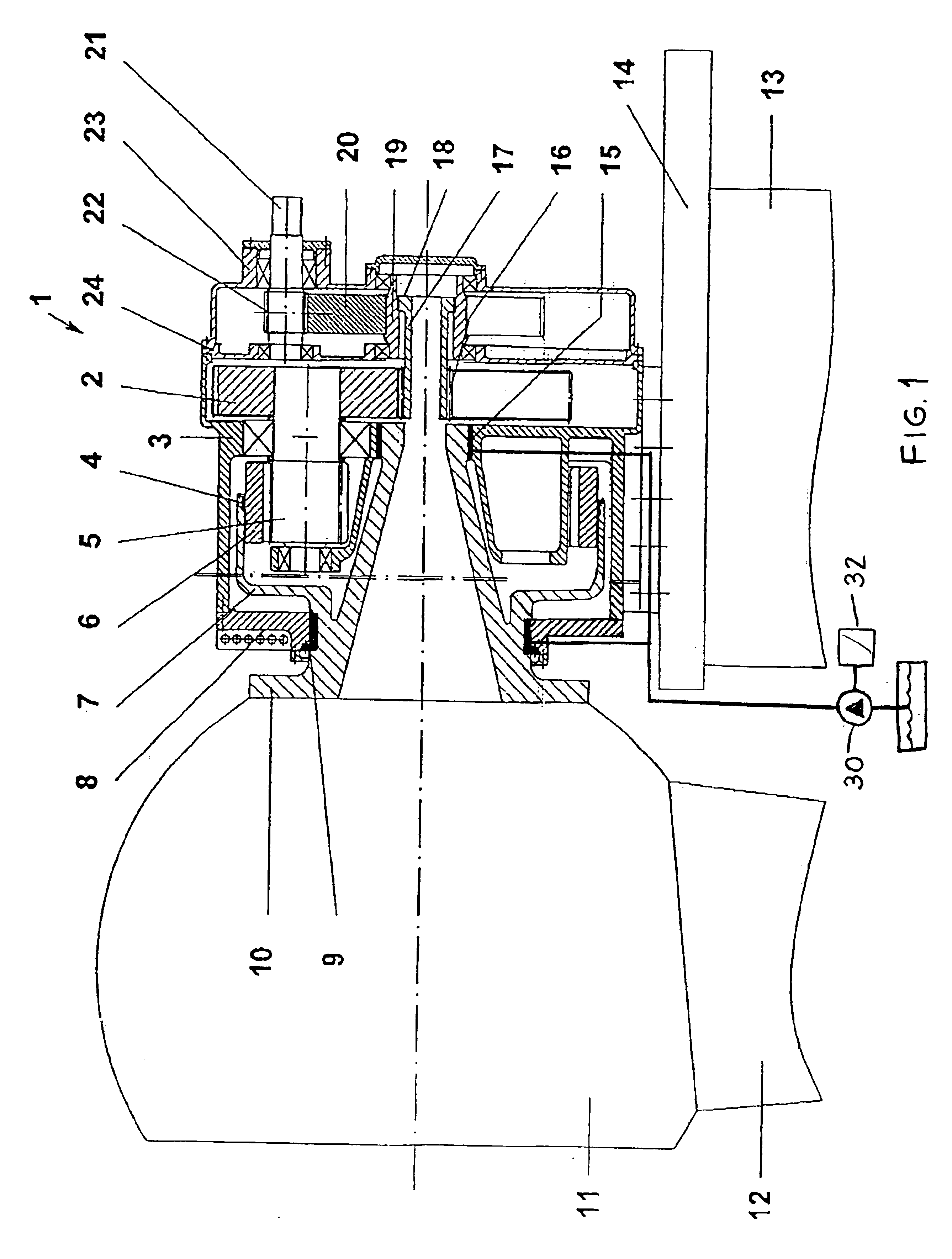
The single FIGURE shows a cut-away view of the top end of the tower (13) of a wind power plant with a rotatable platform (14). The housing (3) of the transmission (1) and a generator (not shown) are secured on the platform (14). However, it is also possible to flange the generator directly to the transmission (1).

The rotary motion produced by the wind is transmitted by the rotor head (11), which carries the blades (12), to a rotor (10). The rotor head (11) is preferably bolted to the rotor (10), but it is also possible to produce the two parts in one piece. The rotor (10) is supported by the housing (3, 8) and mounted rotatably in the housing (3, 8) and provided with an annular gear carrier (7).

The annular gear carrier (7) accommodates the annular gear (6), which transmits the power to one or more planetary gears (5). Each planetary gear (5) is fixed on a respective shaft which is supported by the housing (3) and rotatably mounted at a fixed position in the housing (3). Arranged in ...


PUM


Abstract

A wind-driven rotor is connected to a generator via a multi-stage planetary transmission arrangement and a spur gear stage. The rotor is supported in the housing of the transmission, and an annular gear carrier with an annular gear is arranged directly on the rotor. The transmission represents a compact drive with a high transmission ratio for driving generators by wind power and makes assembly simple.

Description

1. Field of the InventionThe invention relates to a transmission for wind generators of the type having a rotor connected to at least one generator via a multi-stage transmission and a spur gear.2. Description of the Related ArtDE 199 17 605, to which U.S. Pat. No. 6,420,808 corresponds, shows a shaft-mounted transmission for wind generators. This transmission is mounted on a rotor shaft supported in the tower of a wind power plant and is supported on the shaft via two bearings. The transmission housing is attached to the tower of the plant by means of torque arms.The rotor shaft is driven at the end remote from the transmission by a rotor head with wind blades and passes the driving torque into the transmission via an annular gear. The annular gear is secured on the rotor shaft by means of an annular gear carrier and drives the planetary gears of a first planetary stage. The shafts, which are mounted in a manner fixed relative to the housing, each carry a further planetary gear of ...

Claims


Application Information

Patent Timeline
Patent Type & Authority Patents(United States)
IPC IPC(8): F16H1/22F16H1/02F03D11/00F03D11/02F03D15/00
CPCF03D11/02F16H1/227F16H37/041F05B2260/40311Y02E10/722F03D15/00F03D15/10F03D80/70Y02E10/72
Inventor HOSLE, HELMUT
Owner RENK AG
Why Eureka
Try Eureka