Radio frequency amplifying circuit

a technology of frequency amplifying circuit and frequency, applied in the direction of amplifiers with coupling networks, waveguides, amplifiers with semiconductor devices/discharge tubes, etc., can solve the problems of increasing distortion, unsatisfactory value of vswr, and increasing problems, so as to achieve low ripple

Inactive Publication Date: 2004-09-21
TELEFON AB LM ERICSSON (PUBL)
View PDF15 Cites 14 Cited by
  • Summary
  • Abstract
  • Description
  • Claims
  • Application Information

AI Technical Summary

Benefits of technology

to provide a hybrid coupler allowing an amplifying circuit to be produced which has sufficiently low ripple on the supply voltage to be integrated together with more sensitive radio circuits, and which is also insensitive to load mismatch such that an isolator can be avoided.
Differential amplification allows the output current to be shared between four transistors or amplifiers, thus reducing the amplitude of the ripple to a much lower level than that of a one-transistor amplifier. Further, the conducting periods of the four transistors are equally spaced with a 90.degree. phase shift between them, and thus the frequency of the ripple is four times the operating frequency of the circuit, which makes it much easier to filter out the ripple in other parts of the circuit.

Problems solved by technology

Without the isolator the mismatch would result in an unsatisfactory value of the VSWR (Voltage Standing Wave Ratio).
However, the integration of the power amplifier together with the more sensitive parts of the radio circuit will typically result in increased distortion because the power amplifier produces ripple on the supply voltage to the more sensitive circuits.
In addition, this problem increases because of the tendency to use lower and lower supply voltages in such circuits.
However, such power amplifiers are generally driven so strongly that overloading occurs, i.e. they are run in their non linear region in which ripple (pulses) is still produced on the supply voltage.
The benefit of the differential amplifier compared to a one-transistor amplifier is that the amplitude of the ripple is halved and the frequency is doubled, but the result is still not acceptable.
Regarding the removal of the isolator, the power amplifier can be re-biased to keep it in its linear range even with the load mismatch, but this prevents the amplifiers from being driven sufficiently strongly, and it also requires a relatively complicated regulating circuit.
Again, this is an improvement compared to the one-transistor amplifier, but it is still not sufficient.

Method used


Image

  • Radio frequency amplifying circuit
  • Radio frequency amplifying circuit
  • Radio frequency amplifying circuit

Examples


Embodiment Construction

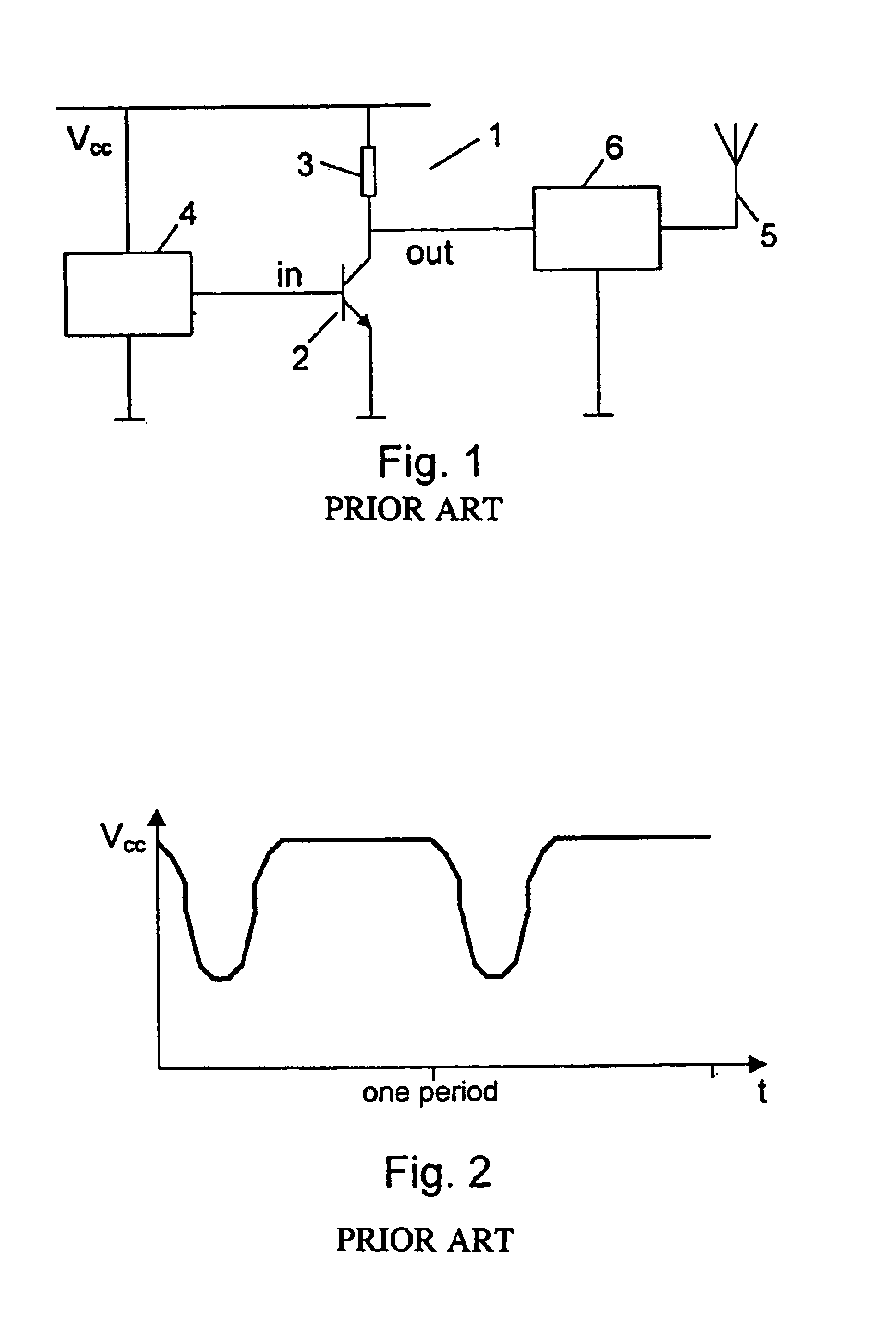
First some prior art circuits will be described for comparison with circuits according to the invention. Thus FIG. 1 shows a prior art power amplifier 1 of the one-transistor amplifier type for use in a portable radio communications device. Although the amplifier in a practical circuit will typically comprise several additional components, it is here illustrated as consisting of a transistor 2 and an impedance 3. The impedance 3 can be any type of impedance, e.g. a current generator having a very high impedance at radio frequencies. The input to the power amplifier 1 comes from a radio circuit 4, and the amplified output is delivered at the out-terminal. The output power from the amplifier is connected to an antenna 5, but because the antenna 5 will normally present an impedance mismatch to the output of the power amplifier 1, an isolator 6 is normally inserted between the output of the power amplifier 1 and the antenna 5 in order to improve the VSWR (Voltage Standing Wave Ratio) of...


PUM


Abstract

A hybrid coupler (66, 67; 72, 73) has four ports and is capable of coupling radio frequency signals having a certain frequency from at least one port to at least one other port. The hybrid coupler (66, 67; 72, 73) is implemented as a differential coupler arranged to couple differential radio frequency signals. With such a hybrid coupler a power amplifying circuit can be produced which has sufficiently low ripple on the supply voltage to be integrated together with more sensitive radio circuits, and which is also insensitive to load mismatch such that an isolator can be avoided. A differential hybrid coupler allows the output current to be shared between four transistors or amplifiers, thus reducing the amplitude of the ripple. Further, the frequency of the ripple is four times the operating frequency of the circuit, which makes it much easier to filter out the ripple.

Description

The invention relates to a hybrid coupler having four ports and capable of coupling radio frequency signals having of a certain frequency from at least one port to at least one other port. The invention further relates to an amplifying circuit comprising such hybrid couplers, and a portable radio communications device comprising such an amplifying circuit. The invention also relates to a method of amplifying radio frequency signals.DESCRIPTION OF RELATED ARTRadio transmitters as they are used in e.g. portable radio communications devices often have a power amplifier (PA) separated from the rest of the radio circuit, and the power amplifier is often connected to an antenna through an isolator which is provided to compensate for an impedance mismatch by the output load (i.e. the antenna) presented to the output of the power amplifier. Without the isolator the mismatch would result in an unsatisfactory value of the VSWR (Voltage Standing Wave Ratio).Especially in portable devices there...

Claims


Application Information

Patent Timeline
Patent Type & Authority Patents(United States)
IPC IPC(8): H01P5/16
CPCH01P5/16
Inventor BRANDT, PER-OLOF
Owner TELEFON AB LM ERICSSON (PUBL)
Why Eureka
Try Eureka