Method and apparatus for acoustically driven media filtration

a technology of acoustically driven media and filtration method, which is applied in the direction of sedimentation settling tank, auxillary pretreatment, separation process, etc., can solve the problems of slow processing rate, high pressure drop, and difficult filtration of fine solid particles, and achieve easy removal and easy collection of particles.

Inactive Publication Date: 2004-09-28
CASE WESTERN RESERVE UNIV
View PDF24 Cites 64 Cited by
  • Summary
  • Abstract
  • Description
  • Claims
  • Application Information

AI Technical Summary

Benefits of technology

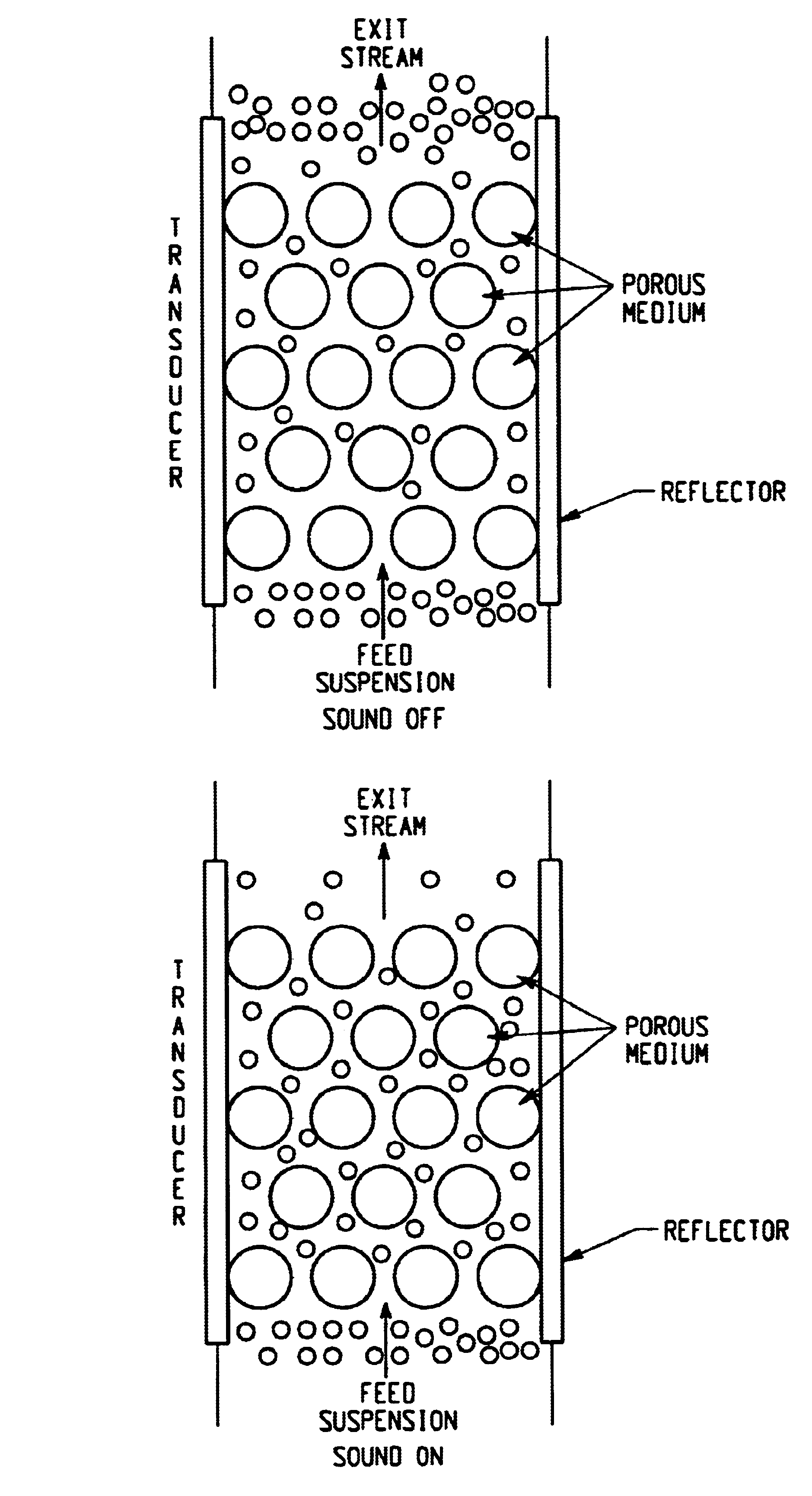
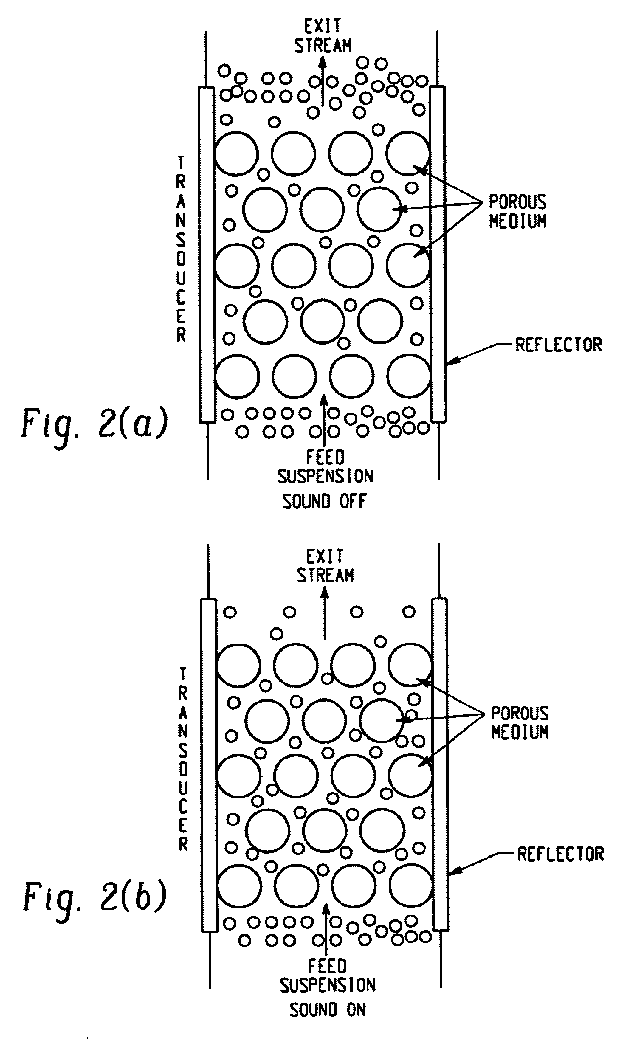
A significant advantage of the present invention is that trapping of small particles is accomplished without an accompanying drop in pressure across the porous medium. A major disadvantage of conventional filtration systems, which rely on small pore sizes to trap small-diameter particles, is the substantial drop in pressure across the porous medium as the trapped particles clog the medium. The trapping mechanism of the present invention operates without such clogging.
As will be shown below, the trapping efficiency of the acoustically activated porous medium increases dramatically immediately after the acoustic field is imposed on the chamber, levels off for a period, and then drops steadily until the porous medium is effectively saturated and unable to trap any additional particles. By selectively activating and de-activating the acoustic field, collection of particles can be facilitated. For example, the exit stream can be switched to a collection circuit during deactivation to harvest the formerly acoustically trapped particles.
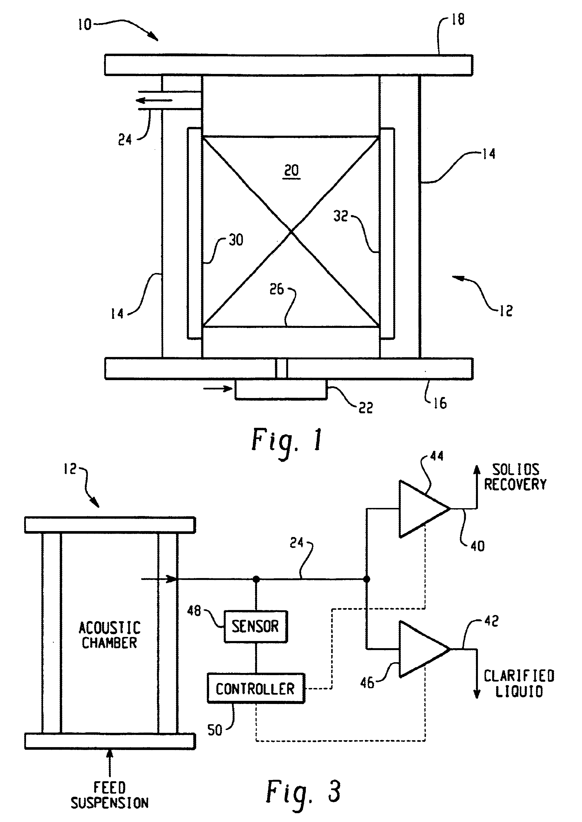
One such collection circuit is shown in FIG. 3, in which fluid outlet 24 is split into two branches, one connected to solids recovery conduit 40 and one to clarified liquid conduit 42. The connections to conduits 40 and 42 are provided by valves 44 and 46, respectively. A sensor 48 connected to controller 50 detects the particle concentration in the chamber effluent flowing through outlet 24. Preferably, sensor 48 incorporates a photodetector that measures the amount of light that can pass through the effluent.
During activation of the acoustic field, particles are trapped in the porous medium contained in the chamber, and controller 50 opens valve 46 to permit flow of the clarified effluent from chamber 12 through conduit 42. After the trapping efficiency of chamber 12 peaks, the effluent leaving the chamber contains an increasing concentration of particles. When sensor 48 detects that the particle concentration in outlet 24 has reached a predetermined minimum value corresponding to an optimum trapping condition, the acoustic field is deactivated, and the fluid stream flushes previously trapped particles out of chamber 12. In addition, controller 50 closes valve 46 and opens valve 44 to connect outlet 24 to solids recovery conduit 42.
Numerous variations of the circuit shown in FIG. 3 can be used in practicing the method of this invention. For example, the deactivation of the acoustic field can be accomplished directly by controller 50 or via another controller that receives a signal from sensor 48 that the threshold particle concentration in the effluent has been reached. Moreover, instead of splitting outlet 24 and employing two valves, a single valve can be used to connect outlet 24 to either solids recovery conduit 44 or clarified liquid conduit 46.
Alternatively, trapped particles can be harvested by removing the porous medium from the chamber 12 while the acoustic field is active; the particles trapped in the porous medium would accompany the medium out of the chamber. One possible way of accomplishing medium removal would be to provide the chamber with a hinged wall that can be opened to remove the medium. If unconsolidated glass beads or other solids are used for the medium, the medium and trapped particles can be readily removed from the chamber by gravity if the hinged wall is disposed beneath the medium.

Problems solved by technology

Filtration of fine solid particles is often very difficult, however, due to the strong interactions between the solids and their host liquid.
In the case of conventional screening methods, high pressure drops or slow processing rates often result from the plugging of membranes or the blocking of pores by the particles.
Furthermore, back-flushing of a membrane to regenerate the filtering medium often is difficult due to strong interactions between the particles and the filter substrate itself.
Moreover, suspensions of immiscible liquid droplets and gas bubbles typically cannot be filtered, as these types of particles are capable of distortion or splitting to pass through the pores in the filtering medium.
These particle-harvesting techniques, however, can be problematic for practical applications.
The first two approaches are difficult to achieve mechanically because of the typical small separation distances involved, and the third technique can be hindered by slow sedimentation rates.
In these applications, however, intense ultrasonic fields are used to create vibrations in the filtering medium (or in the cake formed above the medium) for the limited purpose of preventing or reducing clogging.
Essentially, these ultrasonic fields are applied to free particles from the filtering medium, not to enhance the medium's filtering efficiency.
These methods are limited, however, to particles having certain electrical or magnetic properties and therefore are not suitable for a wide variety of applications.

Method used


Image

  • Method and apparatus for acoustically driven media filtration
  • Method and apparatus for acoustically driven media filtration
  • Method and apparatus for acoustically driven media filtration

Examples


example 1

FIG. 5(a) is a graph showing the variation of particle concentration in the exit stream as a function of time for an experiment involving 0.3 wt % suspension fed at 35 cm.sup.3 / min to the chamber with the transducer operated with 20 W of power. This experiment used the unconsolidated glass beads as the porous medium. In Segment I, the effluent concentration reached a minimum within 1 minute of acoustically energizing the flow field. Thereafter, as the porous medium became saturated, the effluent concentration rose, reaching the original particle concentration after about 9 minutes, indicating the state of full saturation. When clear water was fed in Segment II, the concentration of particles in the effluent dropped over the course of 3 to 4 minutes, but the concentration did not drop to zero. This indicated a continuing leakage of solids from the porous media due to hydrodynamic entrainment. Upon deactivating the field in Segment III, a rapid release of the particles from the chamb...

example 2

The effect of suspension flow rate is shown in FIG. 6 for a 0.3 wt % feed concentration through the glass-bead medium and with the transducer operated at 20 W. As the suspension flow rate was increased from 30 to 45 cm.sup.3 / min, the residence time of the suspension in the porous medium decreased, and therefore one expected to see a decrease in filtration efficiency. FIG. 6 shows that the filtration efficiency was unaffected by the flow rate during initial period, but the time at which the percentage retention reached its peak value and the value of maximum retention decreased with increasing flow rate. The percentage retention for higher flow rates were consistently below those for lower flow rate for the whole duration of Segments I and II.

example 3

The effect of feed concentration is shown in FIG. 7. For this set of experiments, also using the glass-bead porous medium, the flow rate was fixed at 35 cm.sup.3 / min, electrical power was 20 W, and feed concentrations of 0.3, 0.4 and 0.5 wt % were used. In Segment I, there was very little variation in percentage retention for the various feed concentrations. Small differences are seen in Segment II, and these differences can probably be attributed to experimental error. These observations indicate that the filtration is not limited by filling of the available pore volume, at least for the range of feed concentrations tested.


PUM

PropertyMeasurementUnit
diameteraaaaaaaaaa
resonance frequencyaaaaaaaaaa
diameteraaaaaaaaaa

Abstract

A method and apparatus for acoustically enhanced particle separation uses a chamber through which flows a fluid containing particles to be separated. A porous medium is disposed within the chamber. A transducer mounted on one wall of the chamber is powered to impose on the porous medium an acoustic field that is resonant to the chamber when filled with the fluid. Under the influence of the resonant acoustic field, the porous medium is able to trap particles substantially smaller than the average pore size of the medium. When the acoustic field is deactivated, the flowing fluid flushes the trapped particles from the porous medium and regenerates the medium. A collection circuit for harvesting the particles flushed from the porous medium is disclosed. Aluminum mesh, polyester foam, and unconsolidated glass beads are disclosed as porous media.

Description

BACKGROUND OF THE INVENTIONThe present invention relates to a method and apparatus for separating particles from a fluid suspension by filtration. In particular, the present invention relates to an acoustically driven method and apparatus for filtering fine particles in a filtering medium having an average pore size substantially larger than the diameters of the particles being filtered. As used herein, the term "particles" encompasses solids, immiscible liquid droplets, gas bubbles, and other types of discrete matter that might be suspended or entrained in a fluid.Filtration of fluid suspensions containing submillimeter-size particles is of fundamental importance in many chemical and biological processing applications. Conventional separation approaches include physical screening techniques (mechanical sieves, beds of filtration media, or porous membranes in which the fluid passes through pores smaller than the size of the solid particles being collected), gravity-driven methods th...

Claims


Application Information

Patent Timeline
Patent Type & Authority Patents(United States)
IPC IPC(8): B01D24/16B01D24/02B01D21/00
CPCB01D21/0012B01D21/283B01D24/16B01D24/305B01D24/4631B01D24/4853
Inventor FEKE, DONALD L.GUPTA, SANJAYMANDRALIS, ZENON
Owner CASE WESTERN RESERVE UNIV
Why Eureka
Try Eureka