Wall panel assembly and method of assembly

a technology of wall panels and components, applied in the direction of curtain suspension devices, wing arrangements, walls, etc., can solve the problems of large maintenance and construction costs of clean rooms, small clean rooms components may inadvertently drop onto the floor system, and increase the number of wall components and hardware required for a conventional construction. to achieve the effect of facilitating the releasable retention of connection elements

Inactive Publication Date: 2004-10-05
AIRTEX MFG LLLP
View PDF20 Cites 132 Cited by
  • Summary
  • Abstract
  • Description
  • Claims
  • Application Information

AI Technical Summary

Benefits of technology

It follows that once the two panels are positioned adjacent one to another and the connection element is positioned within the passageways of the two panels, the connection member is partially housed within the first panel and partially housed within the second panel to form a linkage or bridging element between the two panels. The connection member may be configured to be dimensionally compressible or contractable within one or both of the respective passageways to effect a pressure fit with the sidewalls of the passageways of one or both of the panels. In preferred constructions the connection member is configured to compress laterally. The creation of this pressure fit in association with the interaction of the securement elements and the connection member facilitate the connection element's releasable retention in place within the passageways of the two panels. The openings in the first panel are correlated with the openings in the second panel whereby a positioning of the connection member within the passages of the two panel members produces an alignment of the openings in both panel members with the respective openings in the connection member.

Problems solved by technology

While an integral structure may present certain structural advantages, oftentimes the limitations in manufacturing and handling techniques and capabilities dictate that a structure may only be constructed by manufacturing smaller elements and thereafter associating those elements one with another to construct the large structure.
Furthermore, the limitations imposed by transportation of the finished structure also in part determine the approach to be taken in constructing a large structural construction.
The need for such closures further increases the number of wall components and hardware required for a conventional construction.
Present construction techniques create several significant problems for clean room construction and maintenance.
During the construction phase of a clean room, small components of the clean room may inadvertently be dropped onto the floor system.
This typically results in the components falling through the floor and out of reach of the installer.
Not only is this very inconvenient but furthermore in some instances this can be hazardous.
A principal cause for downtime is routine cleaning.
Rooms having edges or other surfaces which collect particulates, such as dust, can increase the time required for cleaning operations.
Batten closures are recognized as creating cleaning problems in view of their creating surfaces on which dust may collect.
In rooms of the height mentioned, being composed of multiple panels, serious problems are created with regard to the structural integrity of the wall system itself.
The use of these elongate reinforcement batons has not been altogether satisfactory.
First, the batons are time consuming to install in that each joint must be measured and a respective batons cut to order to meet the particular measurements of a particular joint.
Secondly, the batons have oftentimes proven less than satisfactory in providing the desired degree of structural integrity to the joint.
Lastly surface mounted stiffeners are often unattractive and they create shelves for particulate (dust) to collect on--a feature that is unacceptable in a clean room.

Method used


Image

  • Wall panel assembly and method of assembly
  • Wall panel assembly and method of assembly
  • Wall panel assembly and method of assembly

Examples


Embodiment Construction

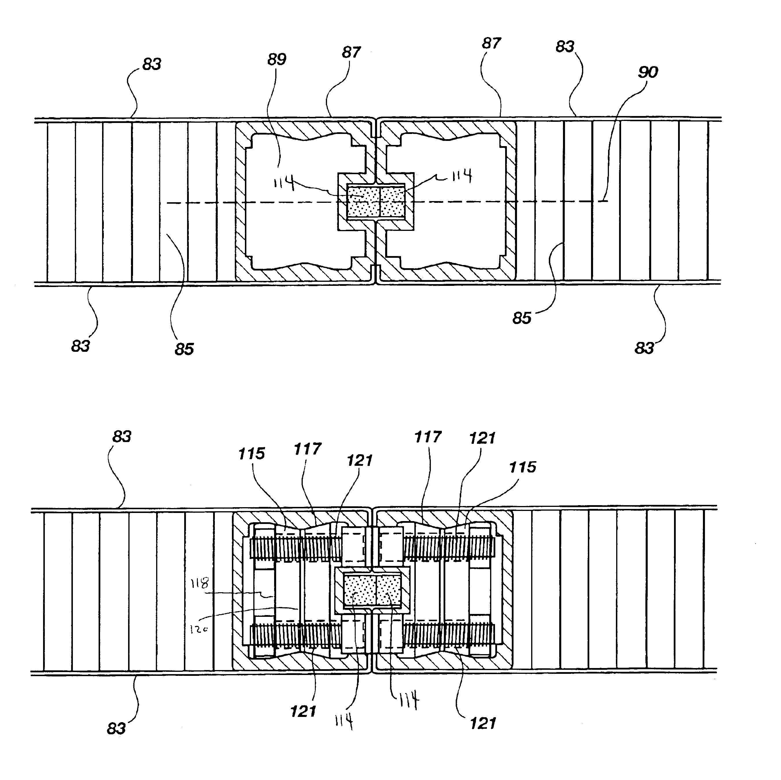
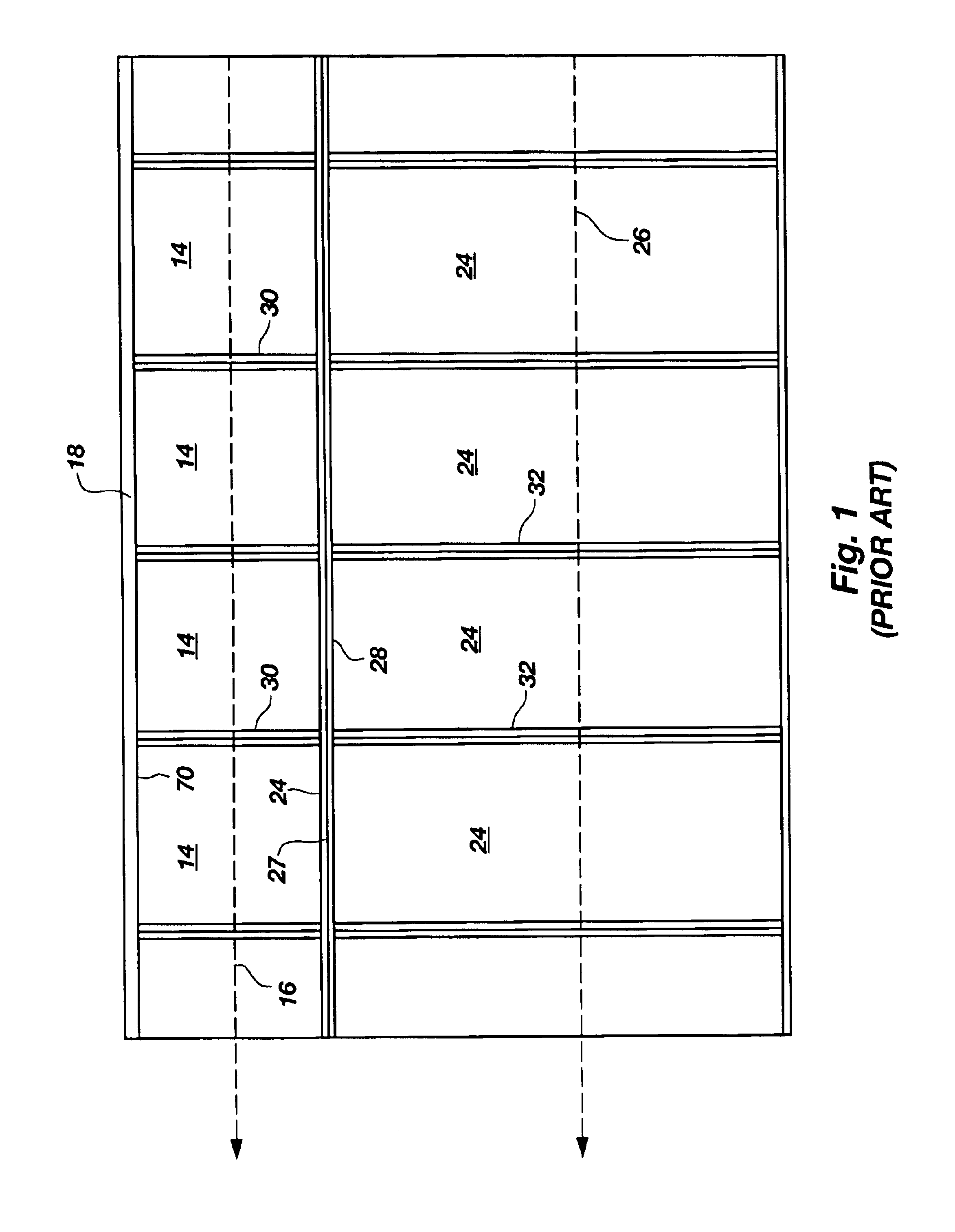
As shown in FIG. 1, a clean room wall panel assembly extant in the art includes a plurality of first panels 14 which are arranged contiguously side to side along a generally linear axis 16 oriented parallel to the ceiling header 18. The uppermost side 20 of each of the first panels 14 engages with the header 18. The opposing side 22 of each first panel 14 engages with a respective second panel 24 which is positioned elevationally below its respective first panel 14. The plurality of second panels are arranged contiguously side to side to form a linear array which extends along a second linear axis 26. Each of the joints or intersections between adjacent first panels, between adjacent first panels and second panels and between adjacent second panels is reinforced by a stiff batten stud element 28. As shown to advantage in FIG. 1 first battens 28 extend to cover the intersection of all of the first panels with their respective second panels. Individual battens 30 are positioned over t...


PUM


Abstract

A wall assembly includes at least two panel elements which are configured for contiguous placement adjacent to one another. Each of the panel elements defines a hollow internal passageway. The panels are configured to permit a contiguous placement whereby the respective passageways of the panels are brought into registration with one another. A connection element is positioned within one of the passageways. The connection element is accessible through a slot defined within the sidewall of the panel wherein the connection element resides. The connection element is slidable whereby it may be displaced partially into the second panel element. The connection element is thereafter actuatable whereby its lateral dimension is decreased to form a pressure fit union with the interior sidewalls of the two passageways. In its spatially decreased configuration, the connection element provides a means of interconnecting the two panel elements together.

Description

BACKGROUND OF THE INVENTION1. FieldThis invention relates to assemblies of panel elements and methods for their assembly. More specifically, the invention is directed to an assembly of panels which may be utilized to form a wall or other structural member together with methods of constructing same.2. State of the ArtVarious structural constructions are formed by the interconnection of various smaller structural elements. While an integral structure may present certain structural advantages, oftentimes the limitations in manufacturing and handling techniques and capabilities dictate that a structure may only be constructed by manufacturing smaller elements and thereafter associating those elements one with another to construct the large structure. Furthermore, the limitations imposed by transportation of the finished structure also in part determine the approach to be taken in constructing a large structural construction.The construction of a wall assembly is one example wherein such...

Claims


Application Information

Patent Timeline
Patent Type & Authority Patents(United States)
IPC IPC(8): E04B2/74E04B9/02
CPCE04B9/02E04B2/7448
Inventor SPRANSY, PETER J.
Owner AIRTEX MFG LLLP
Why Eureka
Try Eureka