
Electromagnetic device

a technology of electromagnetic devices and magnetic fields, applied in the direction of inductances, windings, cores/yokes, etc., can solve the problems of non-uniformity, difficult sealing and monitoring leakage, and temperature differences across the machin

Inactive Publication Date: 2004-11-23
ABB (SCHWEIZ) AG
View PDF749 Cites 21 Cited by
  • Summary
  • Abstract
  • Description
  • Claims
  • Application Information

AI Technical Summary

Benefits of technology

Conventional power transformers, in the lower part of the above-mentioned power range, are sometimes designed with air cooling to carry away the unavoidable inherent losses. For protection against contact, and possibly for reducing the external magnetic field of the transformer, it is then often provided with an outer casing provided with ventilating openings.
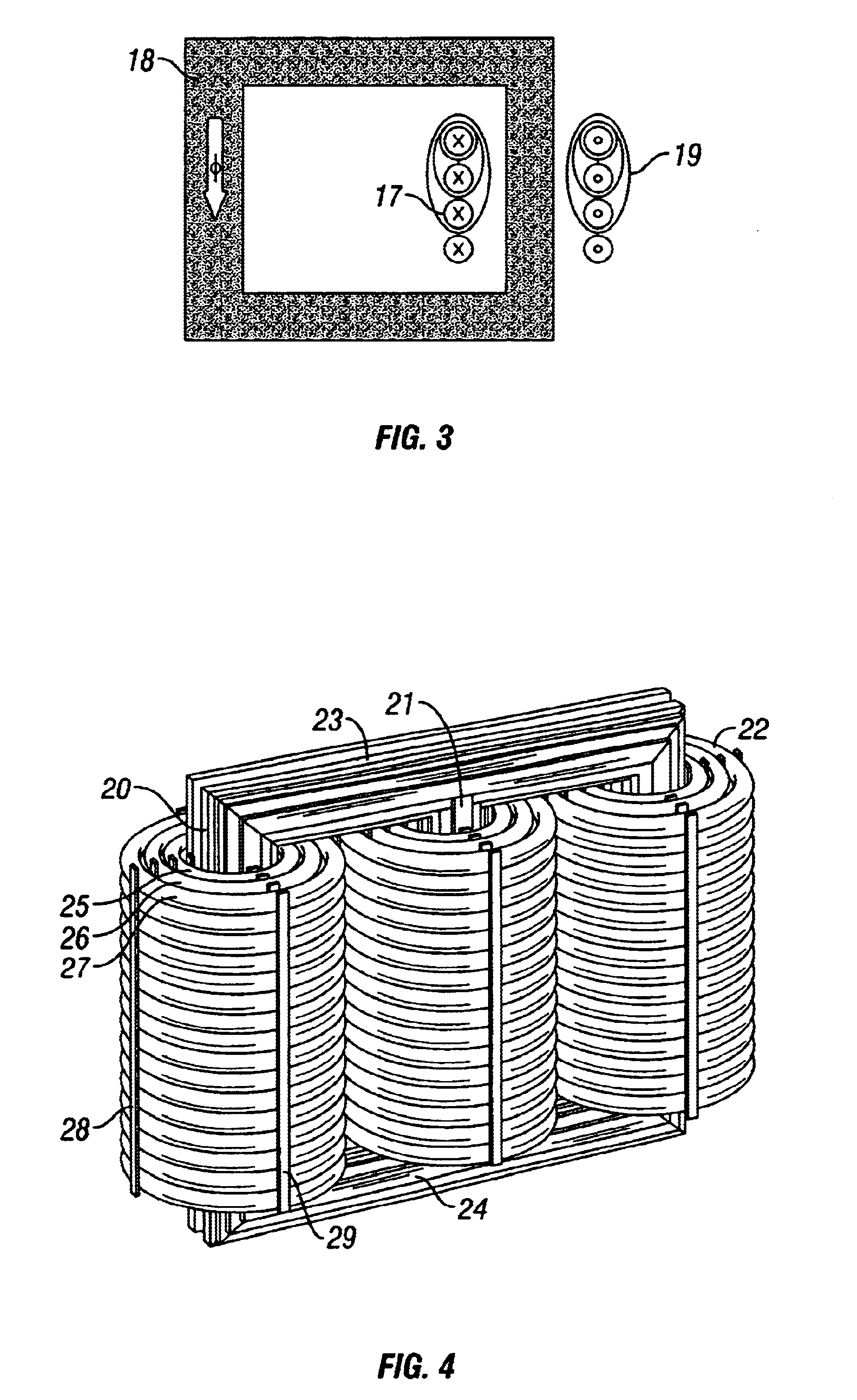
To sum up, thus, a rotating electric machine according to the invention means a considerable number of important advantages in relation to corresponding prior art machines. First of all, it can be connected directly to a power network at all types of high voltage. By high voltage are meant here voltages exceeding 10 kV and up to the voltage levels which occur for power networks. Another important advantage is that a chosen potential, for example ground potential, has been consistently conducted along the whole winding, which means that the coil-end region can be made compact and that bracing means at the coil-end region can be applied at practically ground potential or any other chosen potential. Still another important advantage is that oil-based insulation and cooling systems disappear also in rotating electric machines as already has been pointed out above with regard to power transformers / reactors. This means that no sealing problems may arise and that the dielectric ring previously mentioned is not needed. One advantage is also that all forced cooling can be made at ground potential.

Problems solved by technology

The hydrogen gas has better cooling capacity than air, but difficulties arise at seals and in monitoring leakage.
One problem with large machines is that the cooling tends to become non-uniform and that, therefore, temperature differences arise across the machine.
For mechanical and electrical reasons, a machine cannot be made in just any size.
This sometimes gives rise to corona in the coil-end region, which may be destructive.
The so-called field-controlling points at the coil ends entail problems for a rotating electric machine.
If more than two layers are used, these crossings render the winding work difficult and deteriorate the coil end.
The transformer constitutes an extra cost and also entails the disadvantage that the total efficiency of the system is lowered.
Such cooling systems, however, entail a large number of connections of both oil and electricity at the coil ends.
The thick insulation also entails an increased radius of curvature of the conductors, which in turn results in an increased size of the winding overhang.
Disadvantages with such a large quantity of oil in the system are the risk of leakage and the considerable amount of cleaning work which may result from a fault condition.
The design also exhibits a very narrow radial waist between the different stator slots, which means a large slot leakage flux which significantly influences the magnetization requirement of the machine.
Obvious disadvantages with the proposed solution are that, in addition to requiring a superconducting rotor, it requires a very thick insulation which increases the size of the machine.
This leads to degradation of the oil in the containers.
Failure statistics of conventional oil-filled power transformers show that it is often the on-load tap changers which give rise to faults.
This means that the above-mentioned problems with degradation of the oil because of arcs during operation, etc., effect the whole oil system.
In the current leads of the coils, additional losses arise as a result of the magnetic leakage field around the conductor.
Such an unwanted potential increase may give rise to partial discharges, so-called corona.
Corona may give rise to damage during operation.
Normally, the coils are designed such that the forces arising are absorbed within each individual coil, which in turn may mean that the coil cannot be dimensioned optimally for its normal function during normal operation.
The insulation system of power transformers within the upper power range requires, in addition to a relatively complicated design, also special manufacturing measures to utilize the properties of the insulation system in the best way.
This thus presupposes that the tank which surrounds the transformer is designed for full vacuum, which entails a considerable consumption of material and manufacturing time.
It is obvious that these processes are very time-consuming and cost-demanding and constitute a considerable part of the total time for manufacture and repair while at the same time requiring access to extensive resources.
It is thus obvious that oil together with the cellulose constitutes a non-negligible fire hazard in the case of unintentional heating, for example at an internal flashover and a resultant oil spillage.
It is also obvious that, especially in oil-filled power transformers, there is a very large transport problem.
The tank requires very extensive manufacturing and testing processes and the large external dimensions of the tank also normally entail considerable transport problems;
comprises oil which, in the event of damage or accident, may result in oil spillage leading to extensive environmental damage.
It is known that so-called partial discharges, PD, generally constitute a serious problem for the insulating material in high-voltage installations.
If cavities, pores or the like arise at an insulating layer, internal corona discharges may arise at high electric voltages, whereby the insulating material is gradually degraded and the result could be electric breakdown through the insulation.
This may lead to serious breakdown of the electromagnetic device.
However, also in high voltage cables for transmission purposes, instantaneous potential differences may occur due to transient occurrencies, such as lightning.
The outer layer may, however, not exhibit such conductivity properties that an induced current will flow along the surface, which could cause losses which in turn may create an unwanted thermal load.
This means that no field concentrations can be obtained, neither within sheets, in coil-end regions or in the transition therebetween.
Impregnation of the coils is also an exceedingly complicated and expensive technique when manufacturing rotating electric machines today.

Method used


Image

  • Electromagnetic device
  • Electromagnetic device
  • Electromagnetic device

Examples


Embodiment Construction

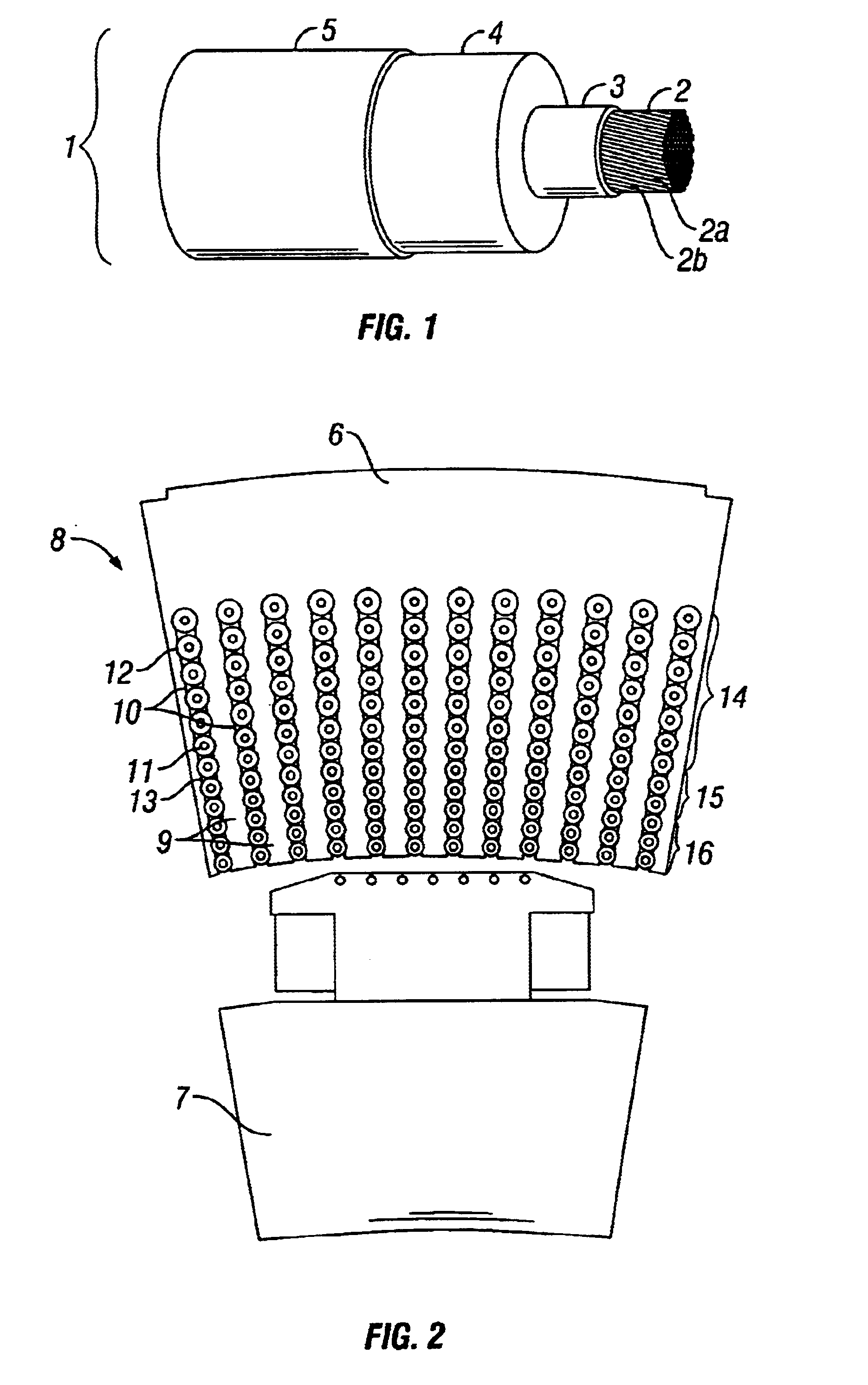
Rotating Electric Machine According to FIGS. 1 and 2

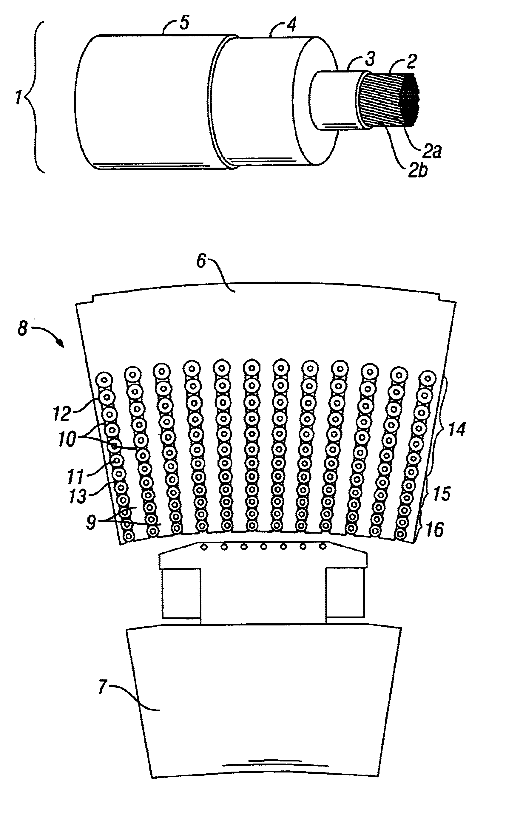
An important condition for being able to manufacture a magnetic circuit in accordance with the description of the invention, is to use for the winding a conductor cable with a solid electrical insulation with an inner semiconducting layer or casing between the insulation and one or more electrical conductors located inwardly therof and with an outer semiconducting layer or casing located outwardly of the insulation. Such cables are available as standard cables for other power engineering fields of use, namely power transmission. To be able to describe an embodiment, initially a short description of a standard cable will be made. The inner current-carrying conductor comprises a number of non-insulated strands. Around the strands there is a semiconducting inner layer. Around this semiconducting inner layer, there is an insulating layer of solid insulation. The solid insulation is formed by a polymeric material with low electrical los...


PUM

PropertyMeasurementUnit
diameteraaaaaaaaaa
areaaaaaaaaaaa
voltageaaaaaaaaaa

Abstract

An electromagnetic device comprises a magnetic field generating electrical circuit including a winding (1) having at least one electrical conductor (2). The winding comprises a solid insulation (4) surrounded by outer and inner layers (3, 5) serving for equalization of potential and having semiconducting properties. Said at least one electrical conductor (2) is arranged interiorly of the inner semiconducting layer (3). The invention also relates to methods for electric field control and production of a magnetic circuit as well as use of a cable for obtaining a winding.

Description

This invention is related to an electromagnetic device for electric power purposes, comprising a magnetic field generating electric circuit including at least one electric conductor having an insulation system. This electromagnetic device may be used in any electrotechnical connection. The power range may be from VA up to the 1000-MVA range. High voltage applications are primarily intended, up to the highest transmission voltages used today.According to a first aspect of the invention a rotating electric machine is contemplated. Such electric machines comprise synchronous machines which are mainly used as generators for connection to distribution and transmission networks, commonly referred to below as power networks. The synchronous machines are also used as motors and for phase compensation and voltage control, in that case as mechanically idling machines. The technical field also comprises double-fed machines, asynchronous converter cascades, external pole machines, synchronous f...

Claims


Application Information

Patent Timeline
Patent Type & Authority Patents(United States)
IPC IPC(8): H01F27/32H01F3/14H01F3/10H01F27/28H01F29/00H01F29/14H01F3/00H01F27/34H02K3/48H02K3/14H02K3/12H02K3/40H02H3/02H02K3/28H02K3/32H02K15/00H02K15/12H02K9/19H02M7/04H01F27/00H02J3/36
CPCH01F3/10H01F27/288H01F27/323H01F27/34H01F29/14H02H3/025H02K3/14H02K3/28H02K3/40H02K3/48H02K15/00H02K15/12H01F3/14Y10S174/25H01F2027/329H01F2029/143H02K9/19H02K2203/15Y10S174/24Y10S174/20Y10S174/13Y10S174/14Y10S174/26H02J3/36
Inventor LEIJON, MATS
Owner ABB (SCHWEIZ) AG
Learn More