Method for optically measuring distance

Inactive Publication Date: 2004-12-28
PERGER ANDREAS
View PDF18 Cites 36 Cited by
  • Summary
  • Abstract
  • Description
  • Claims
  • Application Information

AI Technical Summary

Benefits of technology

It is, therefore, an object of the invention to provide a method of distance measuring, based upon the optical impulse time delay method, of improved signal to noise ratio as a result of received signal summation, which may be realiz

Problems solved by technology

The disadvantage of the known method is that for a ten-fold increase of the signal to noise ratio it is necessary to store 100 sets of received signal scanning values of, for instance, 1,000 scanning values which thus requires 100,000 memory locations.
This requires either powerful application specific integrated circuits (ASICs) or digital signal processors

Method used


Image

  • Method for optically measuring distance
  • Method for optically measuring distance
  • Method for optically measuring distance

Examples


Example

EXAMPLE

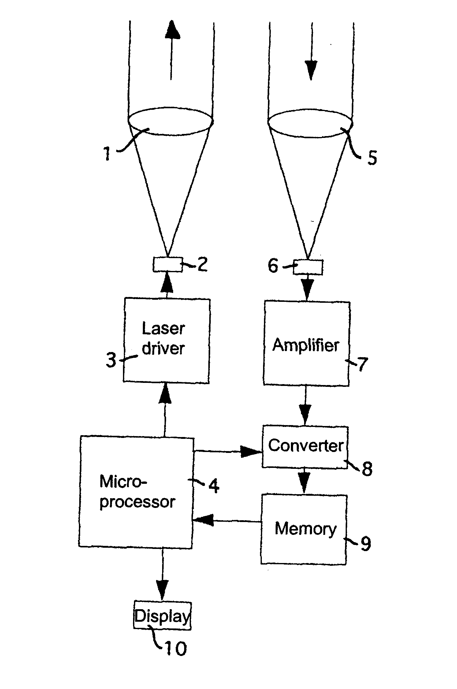
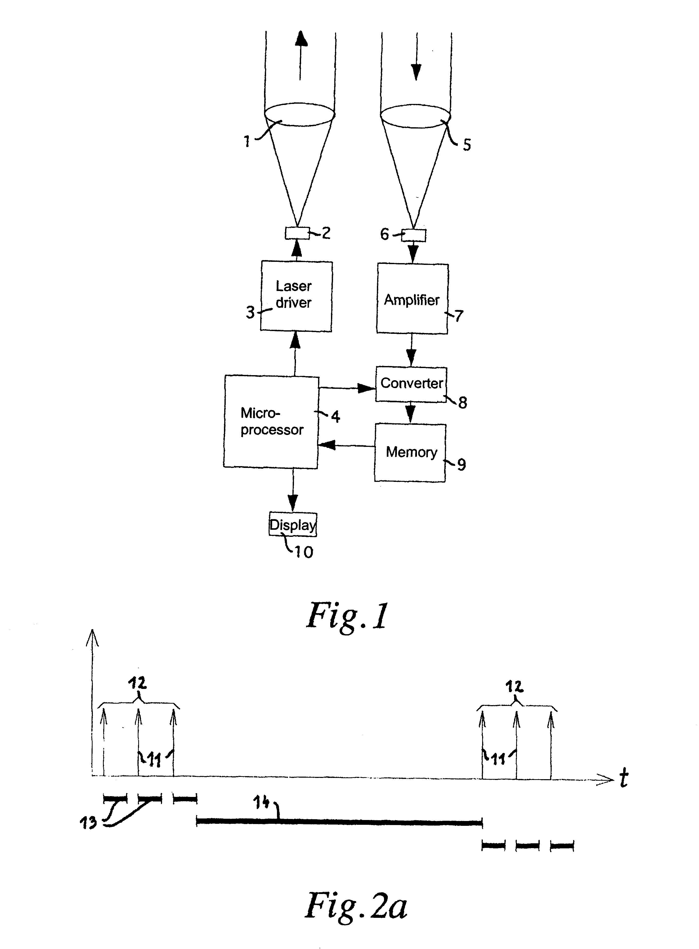
FIG. 2a schematically shows the progress over time of the transmission of laser pulses over a time t.

16 laser pulses are transmitter per pulse train 12. Only the first three pulses are being shown. The transmission rate of the laser pulses 11 in a pulse train 12 was 100 kHz; hence, the spacing between the laser pulses 11 was 10 .mu.s.

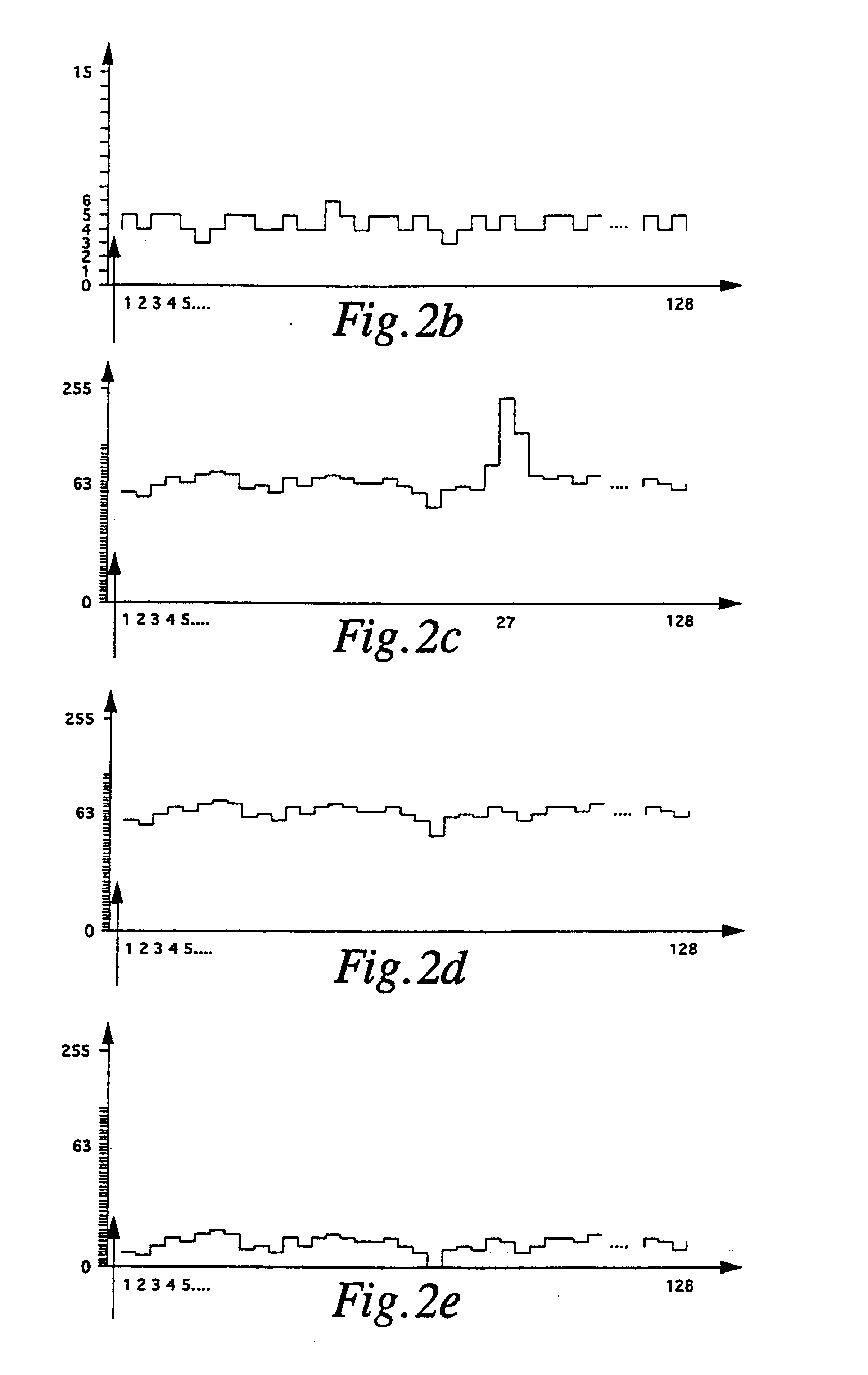
Following each laser pulse 11 the received signal was scanned at 20 MHZ during a measuring time window 13. Each scanning value thus corresponded to 50 ns or 7.5 m. 128 scanning values in a scanning value set were stored, thus corresponding to a measuring time window 13 of 6.4 .mu.s (corresponding to a maximum distance of 960 m).

After 16 laser pulses 11 there was a pause of 1.44 ms duration, and thereafter the next pulse train 12 was transmitted. On chronological average, 16 light pulses were transmitted every 1.6 ms which corresponds to an acceptable value for conventional laser diodes of an average repetition rate of 10 kHz.

The time of the pause...


PUM


Abstract

The invention relates to a method of measuring the distance between a fixed point and an object, by the steps of:a) transmitting a light pulse (11) from the fixed point at a selected instant of transmission;b) periodically scanning of light intensity received at the fixed point and continuously storing, as a set of received scanned signal values, the scanned values at the scanning rate during a predetermined measuring time window (13) embracing the instant of reception of the light pulse reflected from the object;c) repeating steps a) and b) N number of times in order to obtain N number of sets of received signal values;d) summing the individual stored sets of received scanned signal values, set by set, to a summed scanned value set during a calculating window (14) following the N measuring time windows (13);e) repeating steps a) through d) in order to obtain a further summed scanning value set, whereby during or following step d) the further summed scanned value set is added, scanned value set by scanned value set, to the present summed scanned value set to actualize the latter, and whereby an equalizing portion of a summed scanned value set is optionally subtracted therefrom before and/or after the mentioned addition;f) searching within the summed scanned value set for significant scanning values which satisfy predetermined threshold values;g) repeating steps e) and f) until significant scanning values have been detected; andh) determining the looked-for distance from the position of the detected Significant scanning values in the summed scanned value set.

Description

1. Field of the InventionThe present invention relates to a method of measuring the distance between a fixed point and an object by optical pulse time delay measurement, including the steps of:a) transmitting a light pulse from the fixed point at a selected instant of transmission;b) periodically scanning (sampling) of light intensity received at the fixed point and continuously storing, as a set of received scanned (sampled) signal values, the scanned (sampled) values at the scanning (sampling) rate during a predetermined measuring time window embracing the instant of reception of the light pulse reflected from the object;c) repeating steps a) and b) N number of times in order to obtain N number of sets of received signal values, wherein N is an integer equal to or greater than 1;d) summing the individual stored sets of received scanned (sampled) signal values, set by set, to a summed scanned (sampled value set during the calculating time window following the N measuring time windo...

Claims


Application Information

Patent Timeline
IPC IPC(8): G01S17/10G01S17/00G01S7/48G01S7/487G01S17/18
CPCG01S17/107G01S7/487G01S17/18
Inventor PERGER, ANDREAS
Owner PERGER ANDREAS
Why Eureka
Try Eureka