High-Frequency heat-sealing apparatus

a heat sealing and high-frequency technology, applied in the field of high-frequency heat sealing apparatus, can solve the problems of short work life of pressing member, defective sealing, replacement,

Inactive Publication Date: 2005-01-04
SHIKOKU KAKOOKI CO LTD
View PDF22 Cites 9 Cited by
  • Summary
  • Abstract
  • Description
  • Claims
  • Application Information

AI Technical Summary

Problems solved by technology

It is true that achieving satisfactory heat-sealing is made possible by providing a ridge, but it did not mean that providing a ridge solved all problems.
For example, there was a problem that since the face pressure of the long and narrow region being pressed by the ridge reaches approximately 100 kg/cm2, the physical strength of the press region (heat-sealed portion) becomes weak, thereby causing defective sealing, although rarely, by the damage of the press region under the ridge, when the maintenance and adjustment of the press control mechanism of the high-frequency heat-sealing apparatus is insufficient, or when the product being packed is handled in a disorderly manner.
In

Method used


Image

  • High-Frequency heat-sealing apparatus
  • High-Frequency heat-sealing apparatus
  • High-Frequency heat-sealing apparatus

Examples


Embodiment Construction

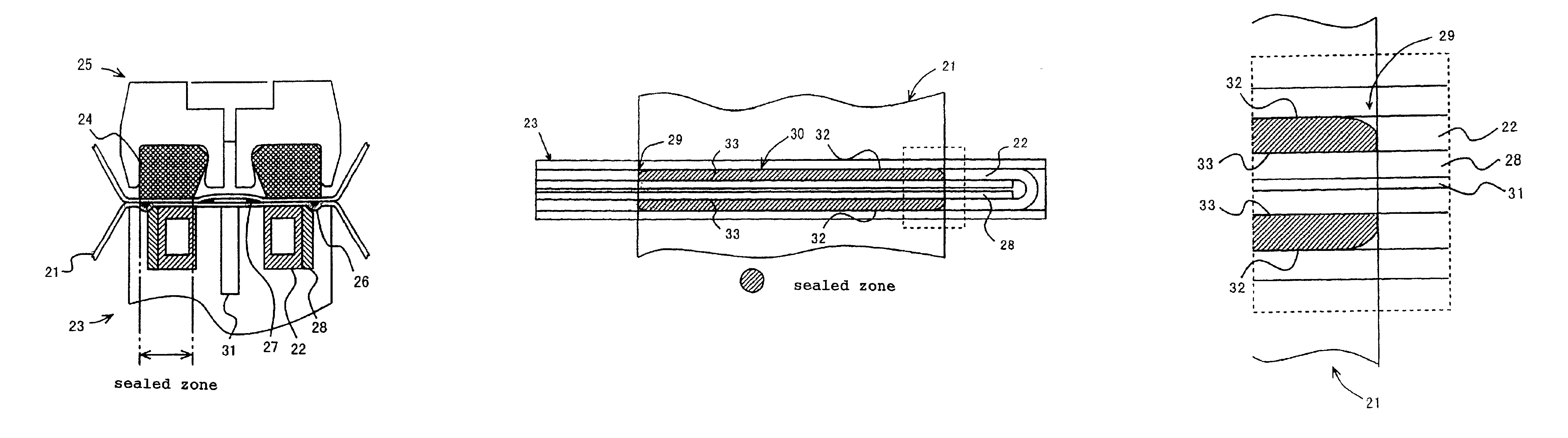
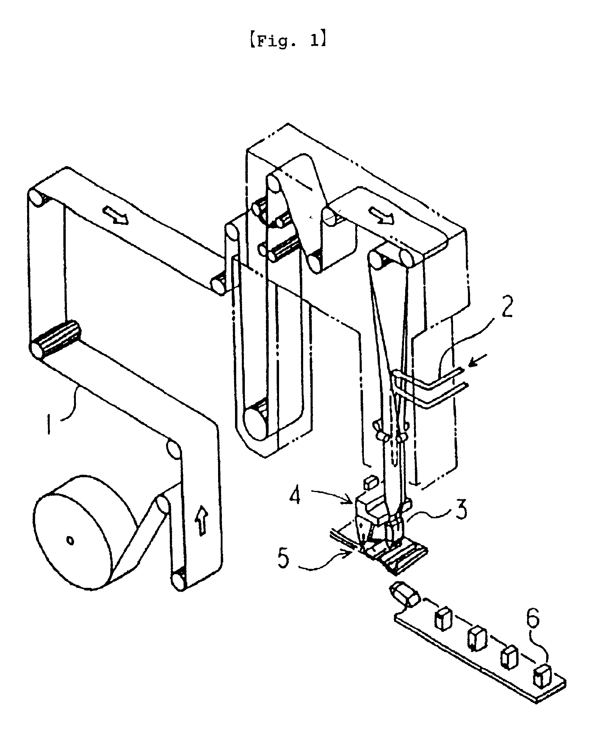
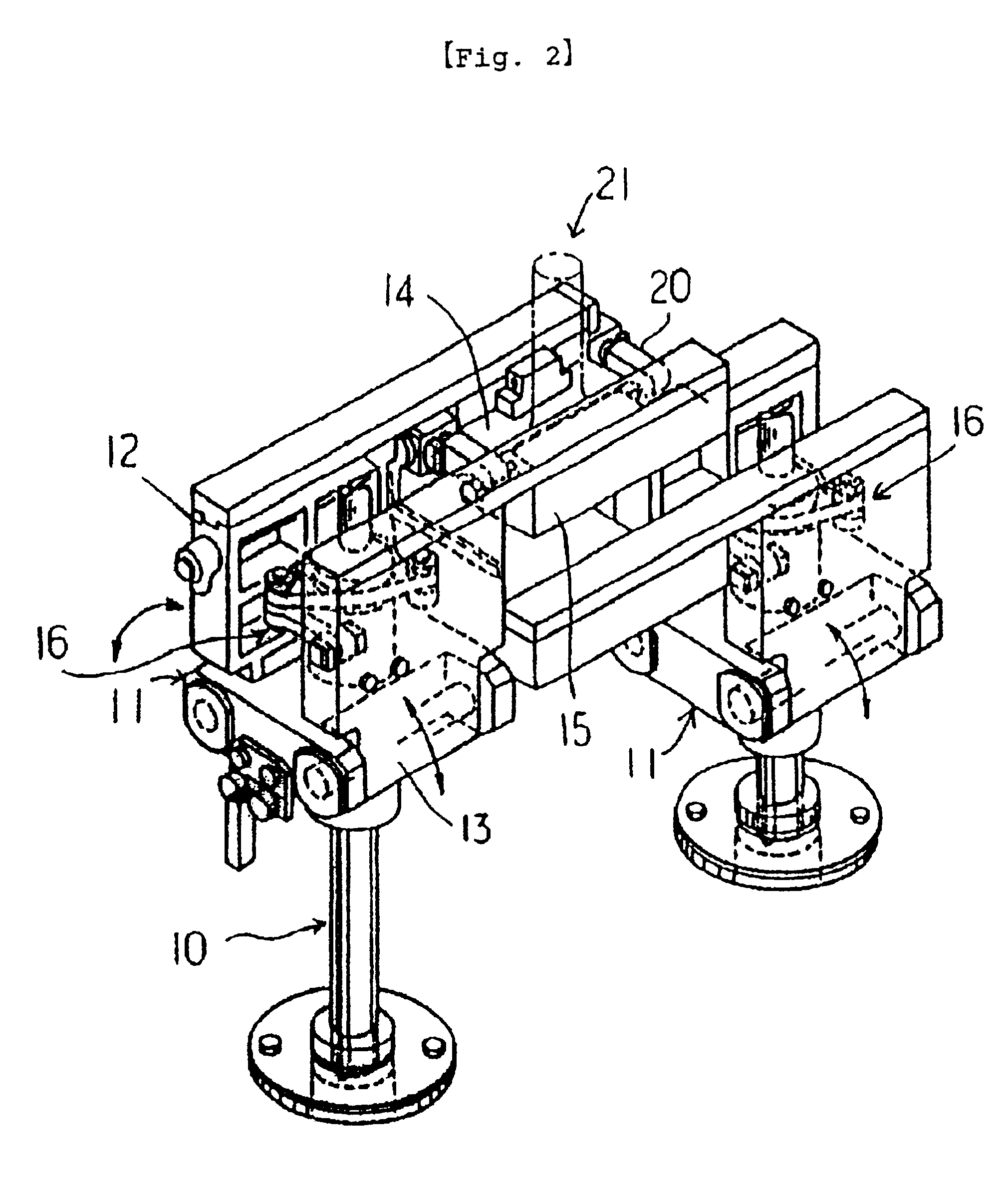
The high-frequency heat-sealing apparatus of the present invention will now be described by referring to the appropriate figure. FIG. 1 is a schematic perspective view of a filling / packing machine wherein the high-frequency heat-sealing apparatus in the present invention is used, FIG. 2 is a perspective view of a transverse sealing apparatus of the filling / packing machine, FIG. 3 is a schematic longitudinal section of the high-frequency heat-sealing apparatus in the present invention, FIG. 4 is a schematic longitudinal section of a high-frequency heat-sealing apparatus of the present invention in a different mode, FIG. 5 is an explanatory diagram of a sealed zone in a high-frequency heat-sealing apparatus, FIG. 6 is an enlarged diagram of a portion of the end portion of a sealed zone in FIG. 5, FIG. 7 is an explanatory diagram of a high-frequency heat-sealing apparatus in the present invention described in FIG. 3, FIG. 8 is an explanatory diagram of a high-frequency heat-sealing app...


PUM

PropertyMeasurementUnit
Widthaaaaaaaaaa
Areaaaaaaaaaaa
Depthaaaaaaaaaa

Abstract

To provide a heat-sealing apparatus capable of achieving an excellent heat-sealing wherein no generation of defective sealing is found even when heat-sealing under severe conditions with a fluid, such as when filling/packing a vegetable juice abundant in water-insoluble vegetable fiber, without providing a ridge on the action face of a high-frequency coil. The high-frequency heat-sealing apparatus consists of a sealing jaw 23 provided with an openable-and-closable high-frequency coil 22 and an opposing jaw 25 provided with a sealing rubber 24 having a flat action face, which transversely heat-seals a tubular packing material with a fluid, wherein a groove 26 inscribed in the end portion on the container's interior side of the sealed zone where both right and left sides are rounded and narrowed, is extended, on the action face of the sealing jaw, over the whole area in the longitudinal direction along the container's interior side of the sealed zone, and a flash portion 27 for a molten resin is formed adjacent to the outer side on the cutting side of the high-frequency coil. The aforementioned groove 26 may be a groove wherein its width partially differs.

Description

BACKGROUND OF THE INVENTION1. Field of the InventionThe present invention relates to a high-frequency heat -sealing apparatus f or use in a filling / packing machine f or producing liquid beverages or the like which are packed in paper containers so that they can be stored for a long time, and more particularly, to a high-frequency heat-sealing apparatus for transversely high-frequency heat-sealing a tubular packing material filled with contents such as liquid beverages, together with a fluid, by using a sealing jaw and an opposing jaw which do not have a ridge on their action faces.2. Description of the Related ArtHitherto, when a packing container having a box shape or the like filled with a liquid such as juice in a sealed manner is to be produced, as seen in Japanese Patent Publication No. 3215 / 1980, it is well known to use a sealing apparatus in which a packing material of a laminate of paper, an aluminum foil and a synthetic resin is used and continuously formed into a tubular s...

Claims


Application Information

Patent Timeline
IPC IPC(8): B29C65/00B29C65/02B65B51/22B29C65/74B65B51/10B29C65/04
CPCB29C65/3656B29C66/81431B29C66/1122B29C66/4312B29C66/72321B29C66/7373B29C66/80B29C66/81457B29C66/849B29C66/8491B65B51/227B29C65/368B29C66/83543B29C66/81427B29C65/3644B29C65/74B29C65/7451B29C66/81811B29C2793/009B29K2023/06B29K2305/02B29L2009/003Y10S53/02B29C65/00B29C65/3668B29C66/244B29C66/71B29C66/72328B29C66/7234B29C66/72341B29C66/73921B29C66/8122B29C66/8126B29C66/81423B29C66/8221B29K2705/02B29K2995/0008B29L2031/7166B29K2821/00
Inventor KUME, SATOSHI
Owner SHIKOKU KAKOOKI CO LTD
Why Eureka
Try Eureka