Plunge slitter with clam style anvil rollers

a technology of anvil rollers and clams, which is applied in the direction of metal working equipment, band saws, manufacturing tools, etc., can solve problems such as interference with proper r

Inactive Publication Date: 2005-01-04
BARRY WEHMILLER PAPERSYST INC
View PDF6 Cites 39 Cited by
  • Summary
  • Abstract
  • Description
  • Claims
  • Application Information

AI Technical Summary

Benefits of technology

Each anvil roller assembly is supported on linear ways extending in the cross machine direction. Each anvil assembly carries a drive motor to move the roller assembly to a commanded position, dictated by the order to be run, and then locked in place. Alternate means for positioning the anvil roller assembly and the cooperating tool head for the slitting blade, such as robotic placement, could also be used. The anvil roller assembly is also supported on a short linear bearing extending in the machine direction that allows adjustment of the position of the anvil rollers to compensate for blade wear. Directly supporting the anvil roller pair is a pivot mechanism having a horizontal pivot axis extending in the machine direction and positioned on the roller assembly center line. This pivot mechanism supports both halves of the roller assembly in a sort of clam shell manner. The two halves of the roller assembly are independently pivotable on the pivot axis and a separate air cylinder joins the two halves to draw them together on cylinder retraction, thereby closing the gap and bringing the upper edges of rollers into contact with the opposite faces of the slitting blade. As the cylinder is retracted and the rollers pinch on the blade, they automatically align themselves with the blade. The clamping air cylinder imposes equal forces on both sides of the blade, as determined by air pressure and the positioning of the cylinder.

Problems solved by technology

Because of this independent repositioning, there may be slight position errors between the slitting blade and the anvil roller slot which could interfere with proper re-engagement.

Method used


Image

  • Plunge slitter with clam style anvil rollers
  • Plunge slitter with clam style anvil rollers
  • Plunge slitter with clam style anvil rollers

Examples


Embodiment Construction

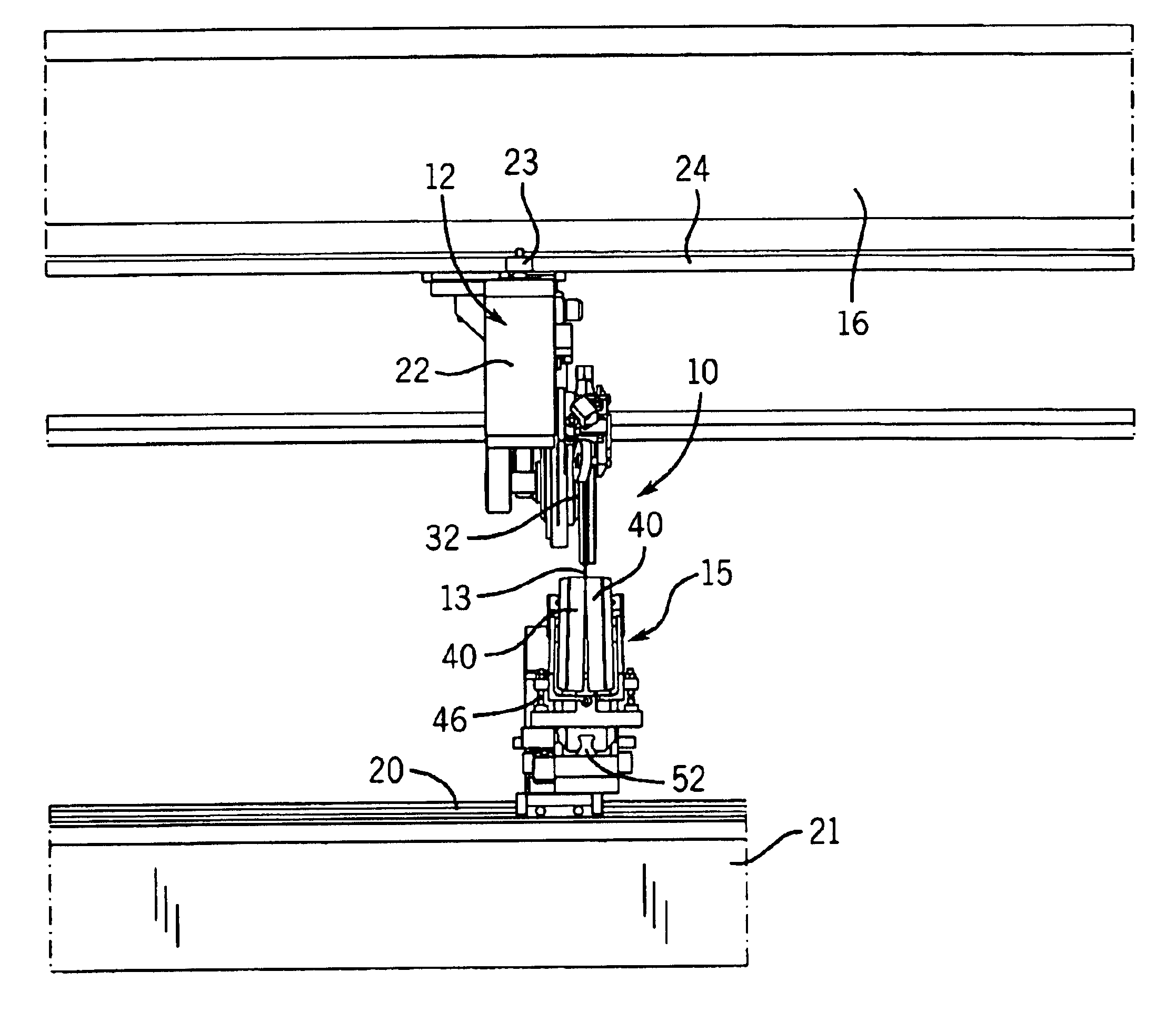
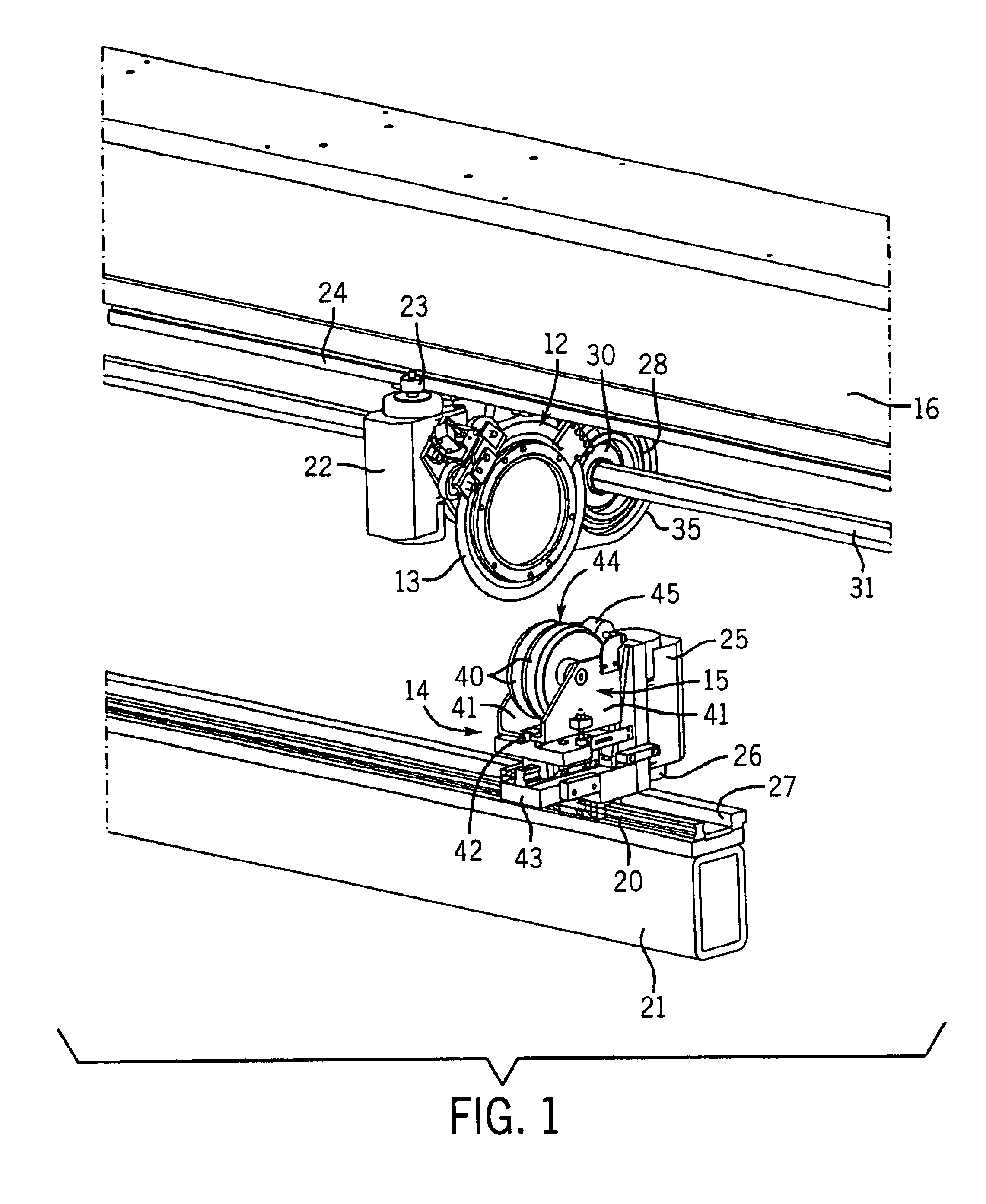
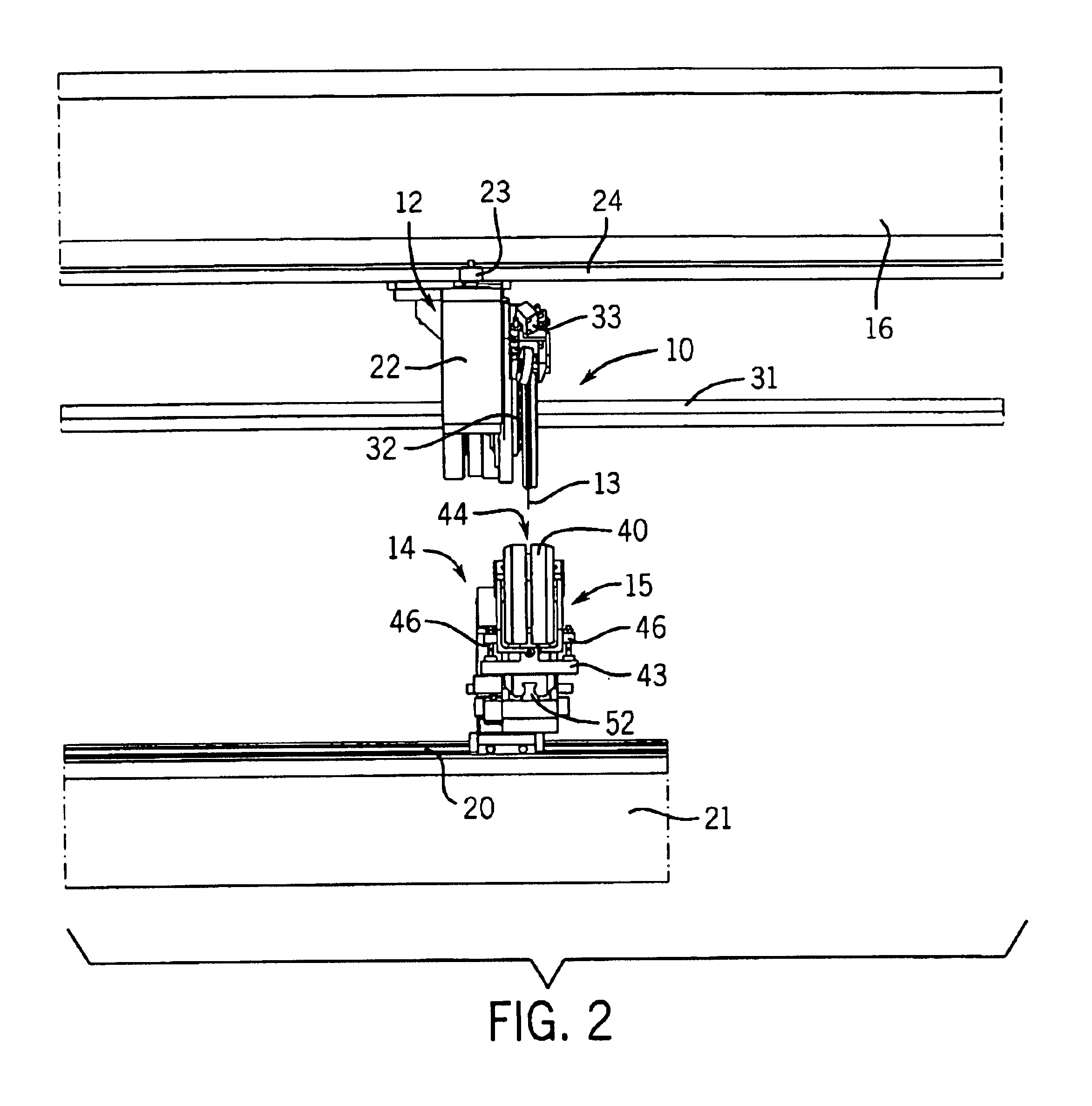
Referring initially to FIGS. 1-3, a web slitting apparatus 10, particularly suited for slitting a moving corrugated paperboard web 11, includes an upper tool head 12 carrying a rotary slitting blade 13 and a lower counterhead 14 carrying an anvil roll assembly 15. The upper tool head 12 is supported for lateral movement in the cross machine direction on a pair of linear bearing ways 17 attached to the underside of an upper box beam 16. Similarly, the lower counterhead 14 is supported for lateral movement in the cross machine direction on a single lower linear way 20 mounted on the upper face of a lower box beam 21.

The upper tool head 12 is moved along the upper linear ways 17 to position the slitting blade 13 by an upper servomotor 22 driving a pinion 23 that engages a linear rack 24 attached to the upper box beam 16 and extending parallel to the linear ways 17.

In a similar manner, lateral positioning of the anvil roll assembly 15 on the lower counterhead 14 utilizes a lower servomo...


PUM

PropertyMeasurementUnit
thicknessaaaaaaaaaa
thicknessaaaaaaaaaa
movementaaaaaaaaaa

Abstract

An apparatus for slitting a running paperboard web includes a thin high speed rotary slitting blade that is plunged through the moving web and into a slot between a pair of anvil rollers supporting the web on the opposite side. Because the slitting blade and the anvil rollers are vertically separated and pre-positioned before order change, an adjustment apparatus is provided to spread the anvil rollers axially apart to provide an open gap with a large target for blade edge when it is plunged through the web and into the slot. The anvil rollers are then closed against the opposite faces of the blade for running operation. Preferably, the anvil rollers are mounted on brackets hinged together below the rollers to move the opposite upper edges of the rollers between the opened and closed position in the manner of a clam shell. The anvil roller assembly is also adjustable in the machine direction to compensate for reduction in rotary slitting blade diameter with blade wear.

Description

BACKGROUND OF THE INVENTIONThe present invention relates to an apparatus for slitting a moving web of corrugated paperboard or the like and, more particularly, to an anvil roller assembly for supporting the running web below and in cooperation with an upper rotary slitting blade.Apparatus for longitudinally slitting a continuous running web of corrugated paperboard is well known in the art. Such apparatus typically also includes a related mechanism for simultaneously providing longitudinal score lines in the advancing web, which score lines facilitate subsequent folding in the construction of paperboard boxes. Thus, a combined slitter-scorer utilizes pairs of rotatable cutting tools and scoring tools disposed in the path of the running web with one tool of each pair disposed on each side of the web. Typically, multiple slitting tools are mounted coaxially and spaced laterally across the width of the web and, likewise, multiple scoring tools are also coaxially mounted and spaced late...

Claims


Application Information

Patent Timeline
Patent Type & Authority Patents(United States)
IPC IPC(8): B26D7/20B26D7/00
CPCB26D7/20B26D2007/202Y10T83/773Y10T83/7809Y10T83/7859Y10T83/7826Y10T83/8886Y10T83/7872
Inventor MICHALSKI, WAYNE A.
Owner BARRY WEHMILLER PAPERSYST INC
Why Eureka
Try Eureka