Method for fabricating bottle molds

a bottle mold and mold technology, applied in the field of molds, can solve the problems of time-consuming and expensive, and achieve the effects of convenient machined, enhanced mechanical interlocking, and local melting

Inactive Publication Date: 2005-01-04
KELLY MACHINE & FOUNDRY
View PDF3 Cites 5 Cited by
  • Summary
  • Abstract
  • Description
  • Claims
  • Application Information

AI Technical Summary

Benefits of technology

When a metallurgical bond is sought between the dissimilar metal insert and the cast iron, it is preferred that a series of ridges be provided on at least one of the surfaces of the dissimilar metal insert blank in the region which becomes embedded in the casting. Such a series of protrusions promotes local melting in the region of the peaks of the ridges, aiding in the metallurgical fusion of the dissimilar metal insert to the cast iron in which the dissimilar metal insert is embedded. To enhance mechanical interlocking of the dissimilar metal inserts in the cast iron, a series of substantially radially extending protrusions w

Problems solved by technology

This problem is of particular concern with the blank bottle molds, where the temperature of the glass is higher.
Shortcomings of

Method used


Image

  • Method for fabricating bottle molds
  • Method for fabricating bottle molds
  • Method for fabricating bottle molds

Examples


Embodiment Construction

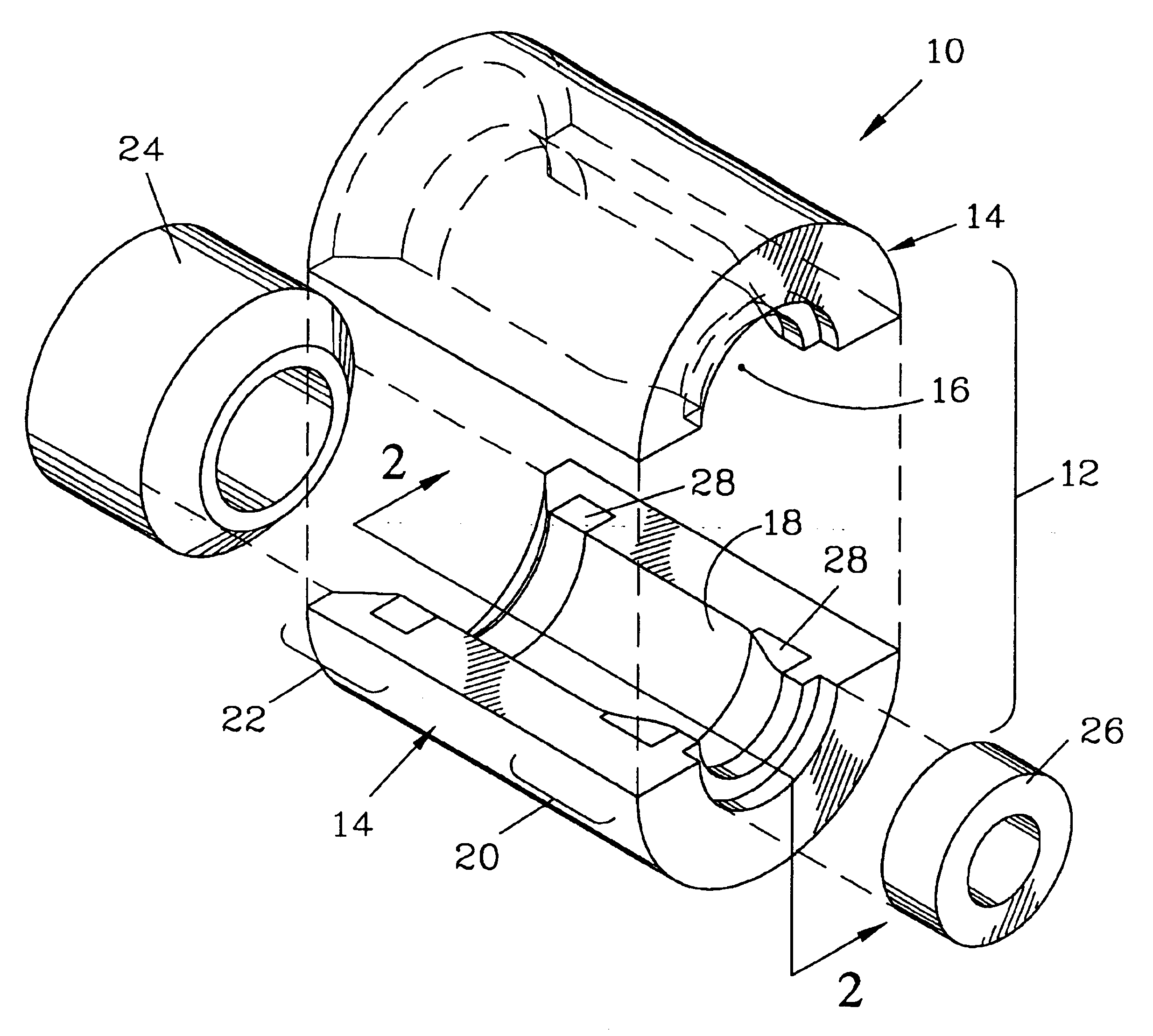
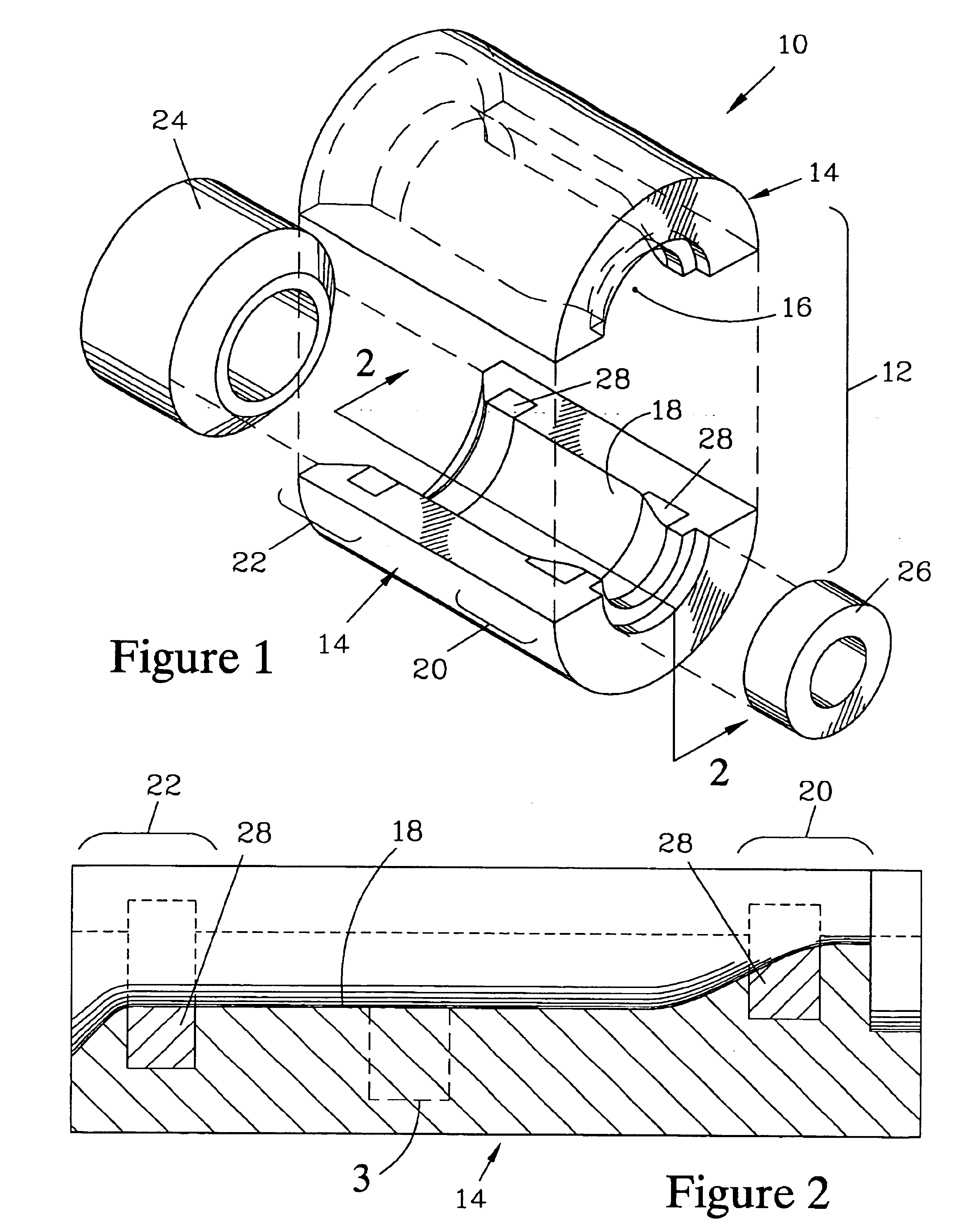
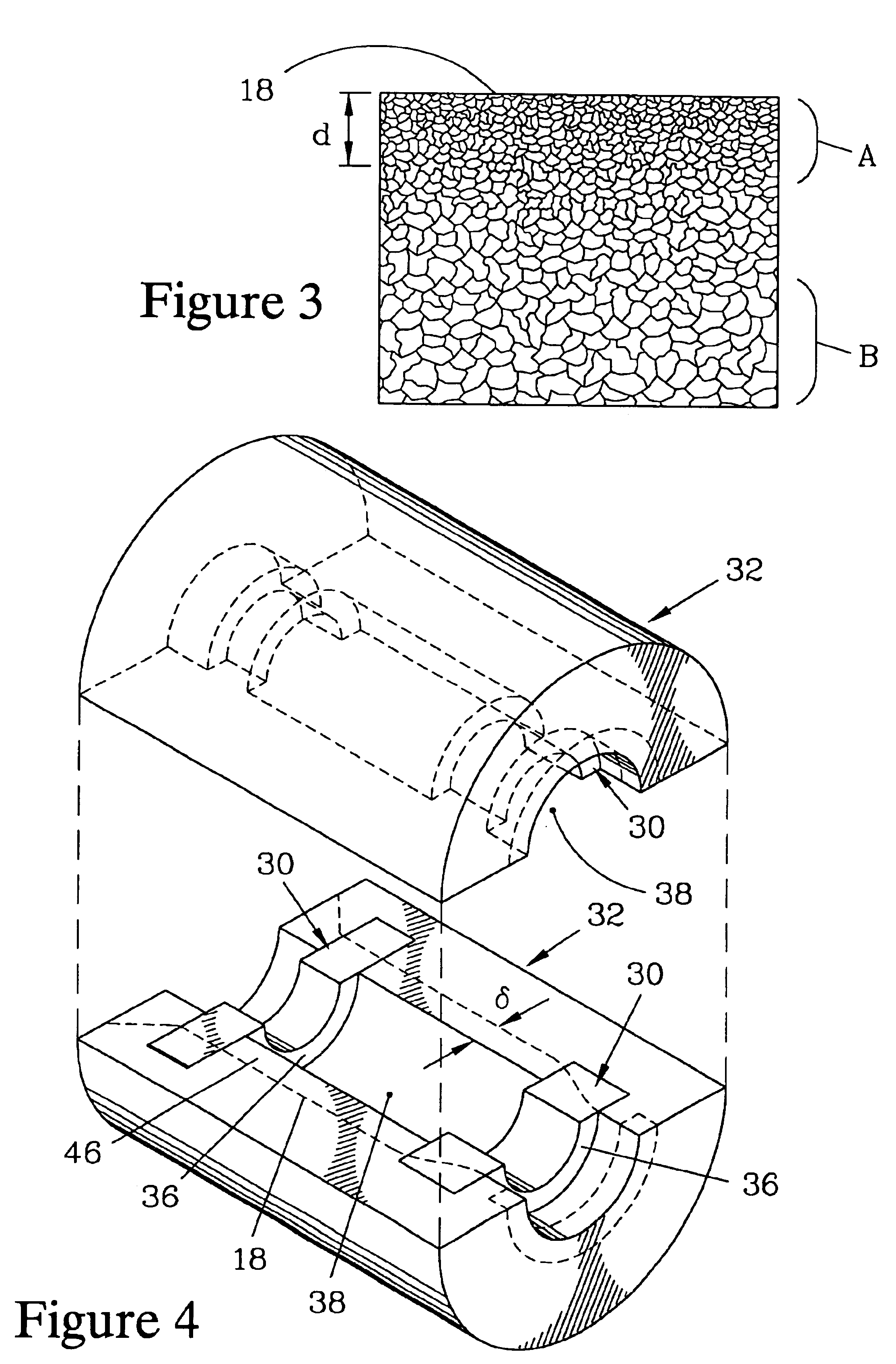
FIG. 1 is an exploded isometric view of a metal blank bottle mold 10 which forms one embodiment of the present invention. The bottle mold 10 has a split mold body 12 having two mating body sections 14, each having a portion of a bottle cavity 16 therein. The bottle cavity 16 is bound by a glass contact surface 18, which passes through a neck region 20 and a baffle region 22 of the bottle mold 10. When a “gob” of glass (not shown) is blown in the bottle mold 10, a baffle 24 and a neck ring 26 are employed to close the bottle cavity 16.

The body sections 14 of the bottle mold 10 are fabricated from cast iron which is well suited to withstand the thermal stress and abrasive action of the “gob” of hot glass as it is blown to form a crude glass shape which conforms to the bottle cavity 16. However, in the neck region 20 and in the baffle region 22, dissimilar metal inserts 28 that are fabricated from a nickel alloy are embedded in the cast iron to provide greater resistance to the action ...


PUM

PropertyMeasurementUnit
Grain sizeaaaaaaaaaa
Lengthaaaaaaaaaa

Abstract

The method allows fabricating a bottle mold having dissimilar metal inserts embedded in regions where the bottle mold is most subject to attack by hot glass, and has a glass contact surface with refined grain size. To fabricate the bottle mold, rough castings are made by pouring cast-iron into a composite mold having dissimilar metal insert blanks fixably positioned therein. The dissimilar metal insert blanks become embedded in the cast-iron matrix to form rough dissimilar metal inserts in the rough casting. The composite mold has regions formed by metal chills that are partially embedded in a sand mix. The chills and the exposed surfaces of the rough dissimilar metal inserts define a cavity surface of the rough casting, which is subsequently machined to provide the glass contact surface of the bottle mold. The chills refine the grain size of the cast iron at the glass contact surface.

Description

FIELD OF THE INVENTIONThe present invention relates to molds for the fabrication of glass bottles and a method of making such molds. More particularly, the invention relates to metal bottle molds which have an extended mold life resulting from the combination of a refined grain structure in the region of the mold which terminates in the glass-engaging surface and from the incorporation of metal inserts of a different composition which form part of the glass-engaging surface, as well as a method of making such improved bottle molds.BACKGROUND OF THE INVENTIONGlass bottles have classically been fabricated by employing metal bottle molds in which the glass bottles are formed. The glass bottles are formed in a two stage process. In the first stage, a “gob” of glass is placed into a blank bottle mold and blown into a crude glass shape having a central cavity. The crude glass shape is then transferred to a final blow bottle mold, in which the crude glass shape is blown to its final shape....

Claims


Application Information

Patent Timeline
IPC IPC(8): B22D19/06C03B9/347C03B9/48
CPCB22D19/06C03B9/48C03B9/347
Inventor DAKAN, SR., JOSEPH D.ELZA, MAX L.
Owner KELLY MACHINE & FOUNDRY
Why Eureka
Try Eureka