Ram air inflated wing

a technology of air inflated wings and rams, which is applied in the direction of emergency apparatus, transportation and packaging, marine propulsion, etc., can solve the problems of bridle lines, unable to achieve sufficient spanwise beam strength, and small pressure differential availabl

Inactive Publication Date: 2005-01-04
LYNN PETER ROBERT
View PDF8 Cites 33 Cited by
  • Summary
  • Abstract
  • Description
  • Claims
  • Application Information

AI Technical Summary

Benefits of technology

Preferably the upper and lower surfaces near each wing tip are adapted so to impart a residual twist that increases the angle of incidence on the wing tips.

Problems solved by technology

In the case of conventional Jalbert or Parapent style foil kites that use ram air inflation as their structural element, the pressure differential available is so small as to allow no possibility of sufficient spanwise beam strength without support from multiple bridles spaced at intervals spanwise.
Bridle lines do however, in themselves, add undesirable drag and can tangle during launching or flying in such a way as to prevent satisfactory operation of the kite.

Method used


Image

  • Ram air inflated wing
  • Ram air inflated wing
  • Ram air inflated wing

Examples


Embodiment Construction

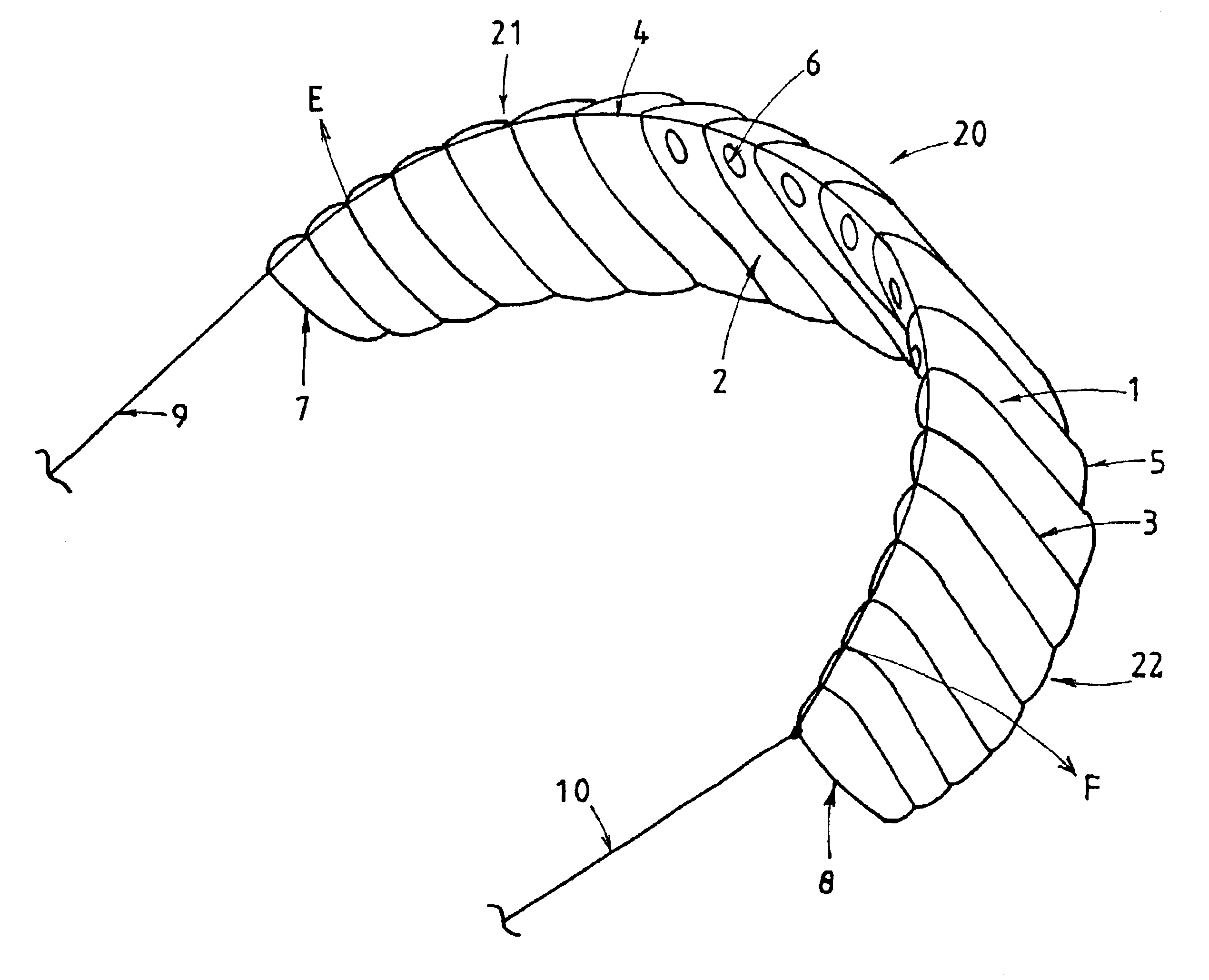
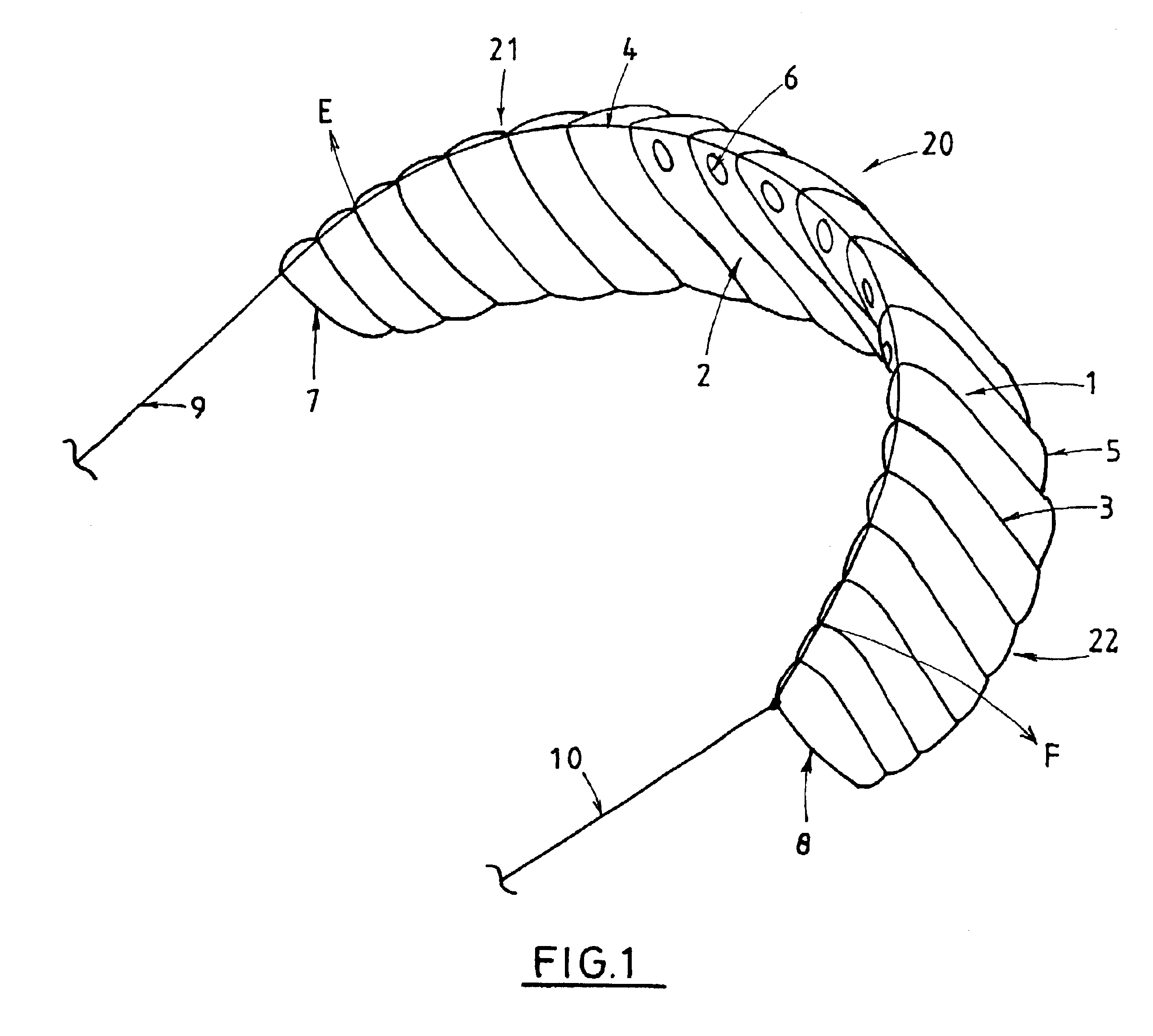
A perspective view of a wing according to the invention is shown in FIG. 1. The wing is a double skinned ram air inflated aerofoil profile wing made from flexible lightweight material. One uniqueness of this wing is that it is able to maintain its spanwise, approximately, semicircular shape without any form of rigid or semi-rigid frame at all and without any flying line attachment directly or indirectly through two or more leg bridling to anywhere on the wing except at or near the wing tips 7 and 8.

The embodiment shown in FIG. 1 is a two line wing with single point line attachment, one at each tip 7 and 8. However, to enable greater control the wing can also be made for use with four flying lines, a front and rear line on each end of tip 7 and a front and rear line on each end of tip 8. There are a number of possible arrangements for flying line attachments and some of these will be discussed later.

The wing is constructed of an upper fabric skin surface 1 and a lower fabric skin sur...


PUM


Abstract

A wing for a traction kite, etc comprises a plurality of cells formed by chordwise-extending ribs (3), valved openings (6) to the cells allowing ram air to inflate the wing. By changing the initial cut-out of the material forming the cells near wing tips (7, 8), compared with that of the cells central to the wing, it is possible to alter the aerodynamic forces at wing tips (7, 8). This allows attachment of flying lines (9, 10) to wing tips (7, 8) only, despite the wing having no framing to maintain its spanwise shape under the loading of flying lines (9, 10). The increased aerodynamic forces at wing tips (7, 8) are achieved by making the aerofoil profiles of the cells progressively more reflexive towards wing tips (7, 8), by giving wing tips (7, 8) a residual twist increasing their angle of incidence, by placing the centres of pressure of the cells near wing tips (7, 8) somewhat forward of the pivot line of the wing, etc.

Description

FIELD OF INVENTIONThe invention relates to aerodynamic devices or wings of a type commonly referred to as kites and in particular to a special category of kite generally referred to as a traction kite, which is used to propel a person across land, ice, snow or water.BACKGROUND OF THE INVENTIONWhile the following discussion and description will be provided in the context of traction kiting, this application is not intended to be limiting. The aerodynamic device of the invention may be used in other flying situations.Unless the context requires otherwise, in the following description the terms “kite” and “wing” are interchangeable and refer to an aerodynamic device that is connected to its operator and / or their ski, skis, skates, board, buggy, or boat, by two or more lines, henceforth called flying lines. These flying lines restrain the kite, allow it to be manoeuvred in the air, and by their extension or shortening relative to each other can be used to effect control of the kite by t...

Claims


Application Information

Patent Timeline
Patent Type & Authority Patents(United States)
IPC IPC(8): B64C31/06B64D17/00B64C31/00B64D17/02
CPCB64C31/06B64D17/02B64C2031/065Y10S244/90Y10S244/902B63H8/14
Inventor LYNN, PETER ROBERT
Owner LYNN PETER ROBERT
Why Eureka
Try Eureka