Amplitude control device for electrical oscillator and electrical oscillator comprising such a device

a technology of amplitude control and electrical oscillator, which is applied in the direction of oscillation generator, pulse automatic control, pulse technique, etc., can solve the problems of deteriorating the spectral quality of the oscillation signal and no noise control

Inactive Publication Date: 2005-01-04
ST ERICSSON SA
View PDF2 Cites 29 Cited by
  • Summary
  • Abstract
  • Description
  • Claims
  • Application Information

AI Technical Summary

Problems solved by technology

This type of circuit has the disadvantage that it copies all the noise of the reference voltage Vref for frequencies within the slaving passband, and that there is no noise control outside this pa...

Method used


Image

  • Amplitude control device for electrical oscillator and electrical oscillator comprising such a device
  • Amplitude control device for electrical oscillator and electrical oscillator comprising such a device
  • Amplitude control device for electrical oscillator and electrical oscillator comprising such a device

Examples


Embodiment Construction

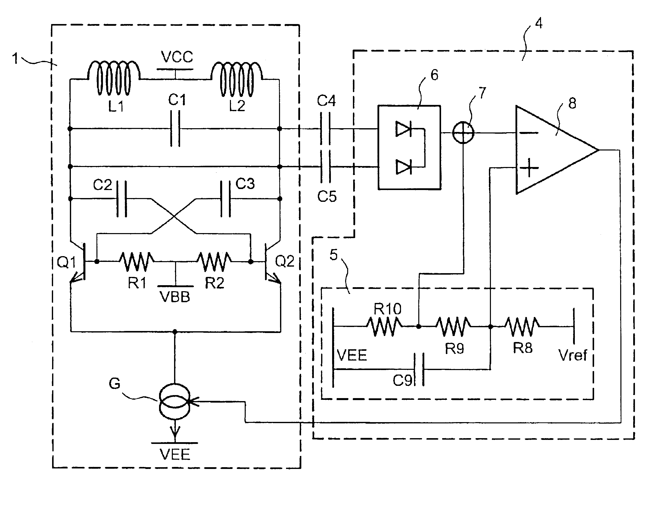
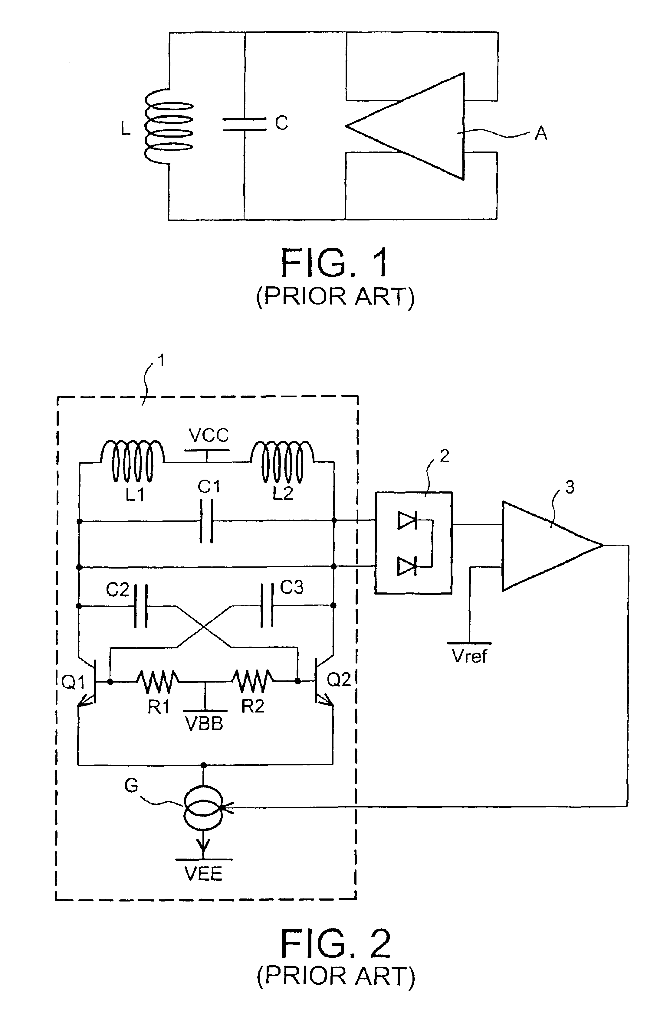
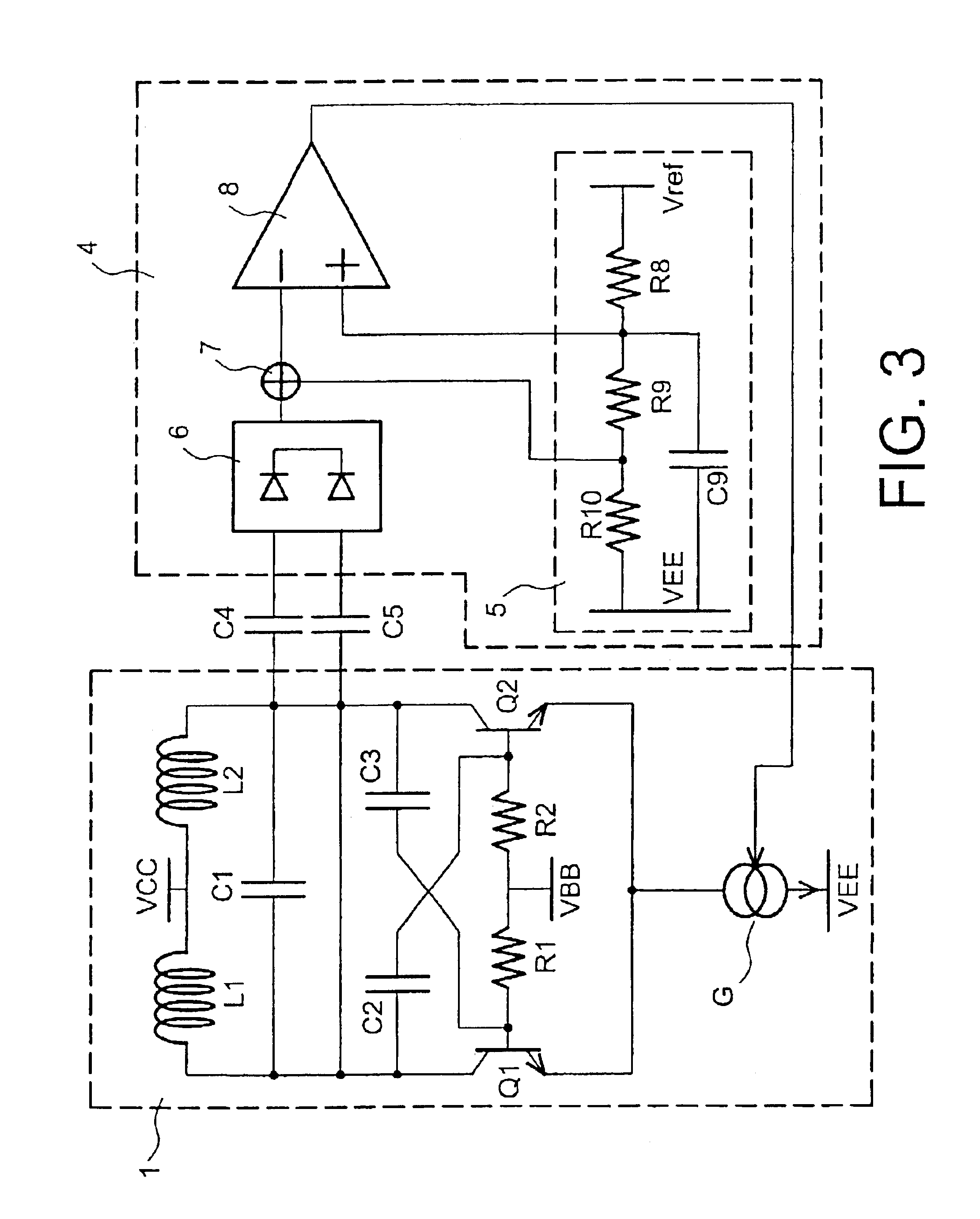
The same references denote the same elements on all figures. FIGS. 1 and 2 have already been described, therefore these figures will not be described again. FIG. 3 shows an electrical oscillator with an amplitude slaving circuit according to the invention. The circuit in FIG. 3 comprises an oscillator 1 and an amplitude slaving circuit 4. The oscillator 1 is identical to the oscillator shown in FIG. 2. The amplitude slaving circuit 4 comprises a voltage divider bridge 5, a rectification stage 6, an adder 7 and a differential amplifier 8.

The input terminals to the amplitude slaving circuit 4 are the input terminals to the rectification stage 6. The amplitude slaving circuit 4 output is the output from the differential amplifier 8. A first capacitor C4 is between the first output terminal of the oscillator 1 and a first input terminal to the rectification stage 6. Similarly, a second capacitor C5 is between a second output terminal of the oscillator 1 and a second output terminal from...


PUM


Abstract

An amplitude control device for a signal output by an oscillator includes a rectification circuit for rectifying the output signal, and a differential amplification circuit for generating a biasing current control signal for the oscillator. The biasing current control signal is based upon the output signal from the rectification circuit and a reference voltage. A dividing bridge and an adder are designed so that only a fraction of the reference voltage is used to define the amplitude of the oscillations. The contribution made to the oscillator phase noise by the reference voltage noise is considerably reduced.

Description

FIELD OF THE INVENTIONThe present invention relates to an amplitude control device for an electrical oscillator, and an electrical oscillator comprising such a device.The present invention is applicable to radio communication systems, and more particularly, to mobile telephone systems, such as GSM, DCS, PCS, UMTS, etc.BACKGROUND OF THE INVENTIONAn electrical oscillator is a circuit that produces an electrical signal at a frequency defined by a time constant specific to it. FIG. 1 illustrates a principle diagram for an electrical oscillator that includes an inductance L, a capacitor C and a holding amplifier A. The oscillator time constant is equal to √{square root over (LC)} and the oscillation frequency is equal to ½π√{square root over (LC)}.The amplitude of voltage oscillations measured at the terminals of the LC circuit is determined by non-linearities of the holding amplifier. It is important to check the amplitude of the voltage oscillations to achieve correct interfacing betwe...

Claims


Application Information

Patent Timeline
IPC IPC(8): H03L5/00
CPCH03L5/00
Inventor RAMET, SERGE
Owner ST ERICSSON SA
Why Eureka
Try Eureka