RFID transponder having active backscatter amplifier for re-transmitting a received signal

Inactive Publication Date: 2005-01-04
INTERMEC IP
View PDF21 Cites 262 Cited by
  • Summary
  • Abstract
  • Description
  • Claims
  • Application Information

AI Technical Summary

Benefits of technology

In accordance with the teachings of the present invention, an RFID transponder is provided that includes an active backscatter amplifier which a

Problems solved by technology

A drawback of all such communication systems is that the radiated power becomes attenuated over distance.
Repeater systems are advantageous for many applications, but nevertheless add cost and complexity to a communication system that would be unacceptable for many applications.
Another drawback is that it is necessary to maintain isolati

Method used


Image

  • RFID transponder having active backscatter amplifier for re-transmitting a received signal
  • RFID transponder having active backscatter amplifier for re-transmitting a received signal
  • RFID transponder having active backscatter amplifier for re-transmitting a received signal

Examples


first embodiment

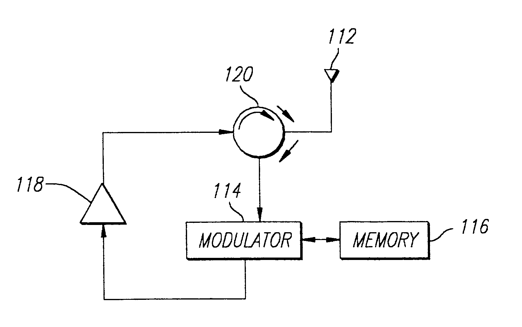
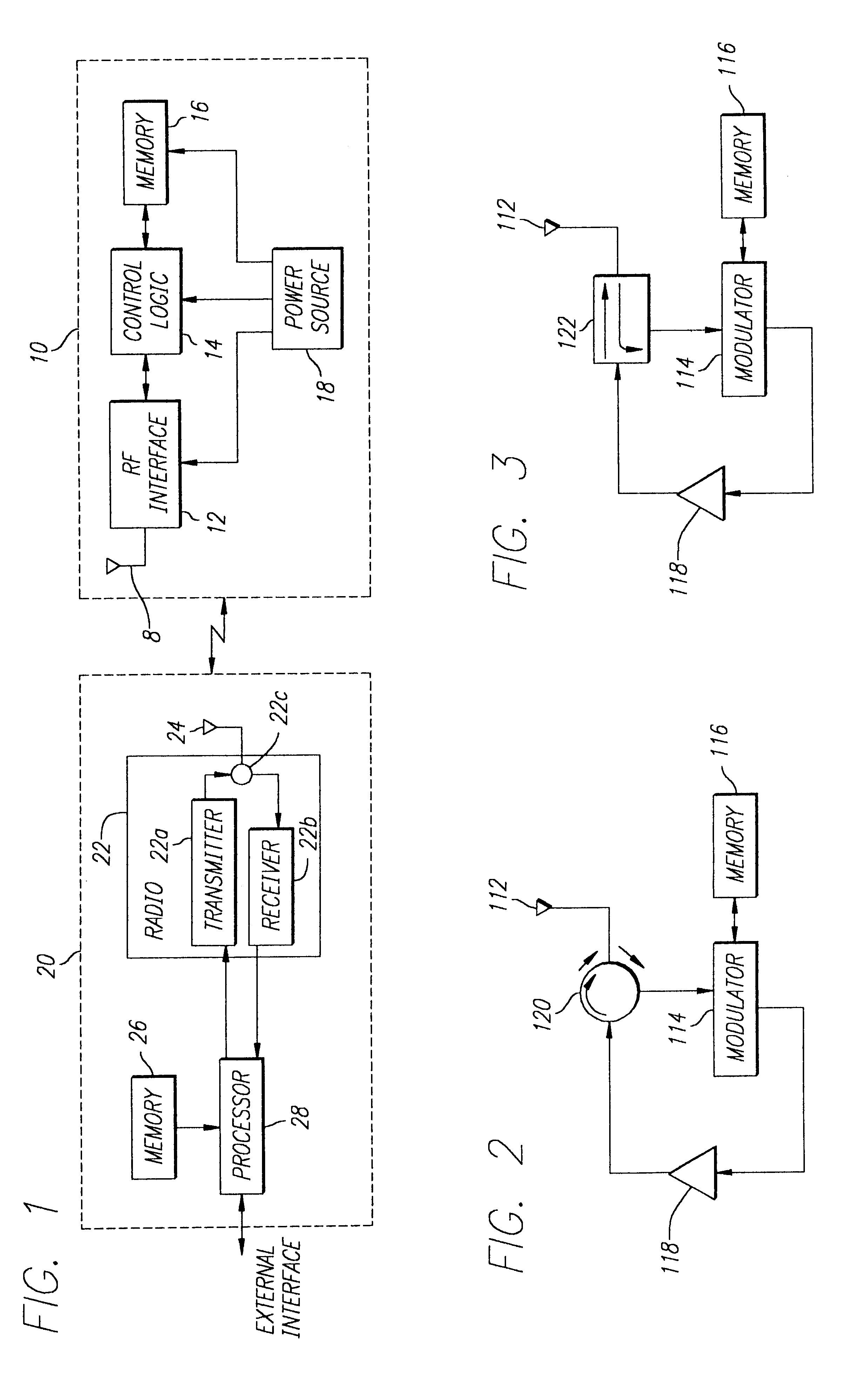
Referring now to FIG. 2, a block diagram of an RFID transponder in accordance with the invention is illustrated. The RFID transponder comprises an antenna 112, a circulator 120, a modulator 114, a memory 116, and an amplifier 118. The circulator 120, modulator 114, memory 116, and amplifier 118 may be disposed on an integrated circuit chip that is disposed on a substrate (not shown). The antenna 112 may be integrally formed on the substrate. Preferably, the antenna 112 comprises thin (e.g., 18 to 35 microns thickness) lines formed of a conductive metal, such as copper. These lines may be formed by plating or adhering or screening a thin layer of copper (or other conductive metal) onto the substrate. This layer may then be etched to form the specific geometric configuration (e.g., dipole, folded dipole, loop, coil, spiral, meander, and the like) of the antenna. Similarly, one or more impedance adjustment elements may be integrally formed on the substrate to modify the impedance of th...

second embodiment

Referring now to FIG. 3, a block diagram of an RFID transponder in accordance with the invention is illustrated. The RFID transponder of FIG. 3 is similar in construction to the RFID transponder of FIG. 2, except that a directional coupler 122 is used in place of the circulator 120. The directional coupler 122 permits simultaneous RF communications therethrough in opposite directions. Accordingly, a signal from the antenna 112 passes through the directional coupler 122 to the modulator, and an amplified signal from the amplifier 118 passes through the directional coupler to the antenna. Alternatively, a power divider could be utilized in place of the directional coupler 122, or the antenna 112 could be directly coupled to the modulator 114 and amplifier 116 without any intermediary device. It should be appreciated that such embodiments would likely not operate as efficiently as the electronic circulator 120 of FIG. 2 or the directional coupler 122 of FIG. 3 due in part to impedance ...

third embodiment

Referring now to FIG. 5, a block diagram of an RFID transponder in accordance with the invention is illustrated. The RFID transponder of FIG. 5 is generally similar to the embodiments described above, but further includes an ability to receive data as well as transmit data, and therefore provides data read and write capability. The RFID transponder comprises an antenna 112 and circulator 120 as described above with respect to FIGS. 2 and 4. In addition, the RFID transponder includes a data detect block 132, a data decode block 134, a processor 136, an amplifier 138, a modulator 142, and a filter 144. The circulator 120 has a first port connected to the antenna 112, a second port connected to the data detect block 132 and a third port connected to the filter 144. The data detect block 132 is connected to the data decode block 134 and the amplifier 138. The amplifier 138 is connected to the modulator 142, which is in turn connected to the circulator 120 through the filter 144. The pro...


PUM


Abstract

An RFID transponder is provided with an active backscatter amplifier that amplifies and re-transmits a received signal. The RFID transponder comprises an antenna and a circulator having a first port connected to the antenna. A modulator is connected to a second port of the circulator. An amplifier is connected to a third port of the circulator, with the amplifier connected to the modulator. An RF signal impinging upon the antenna passes through the circulator, the amplifier, and the modulator, and returns to the antenna through the circulator. The modulator further comprises an input coupled to the second port of the circulator and an output coupled to an input of the amplifier. The amplifier has an output coupled to the third port of the circulator. The modulator is adapted to modulate the RF signal using on-off keying.

Description

BACKGROUND OF THE INVENTION1. Field of the InventionThe present invention relates to radio frequency (RF) communications, and more particularly, to an RFID transponder having an active amplifier that receives a signal, and then amplifies and re-transmits the received signal on the same frequency.2. Description of Related ArtWireless communication systems that communicate signals over the RF spectrum are well known in the art. Such systems have numerous diverse applications, including cordless and cellular telephones, paging, wireless computer networks, mobile radio for police, fire and municipal services, remote control devices for garage doors and other devices, and remote data sensing, to name just a few. A drawback of all such communication systems is that the radiated power becomes attenuated over distance. Accordingly, it is known to introduce one or more amplifier units between a source and destination of an RF signal, known as repeaters. Such repeater stations amplify and ret...

Claims


Application Information

Patent Timeline
IPC IPC(8): G06K19/07
CPCG06K19/0723
Inventor MAYS, WESLEY M.MOORE, BRAD DAVID
Owner INTERMEC IP
Why Eureka
Try Eureka