Encapsulated electrophoretic displays having a monolayer of capsules and materials and methods for making the same

a technology of electrophoretic display and capsule, which is applied in the field of materials and methods for forming a monolayer of capsules for an encapsulated electrophoretic display, can solve the problems that current displays are not capable of achieving uniform brightness or good contras

Inactive Publication Date: 2005-01-04
E INK CORPORATION
View PDF533 Cites 581 Cited by
  • Summary
  • Abstract
  • Description
  • Claims
  • Application Information

AI Technical Summary

Benefits of technology

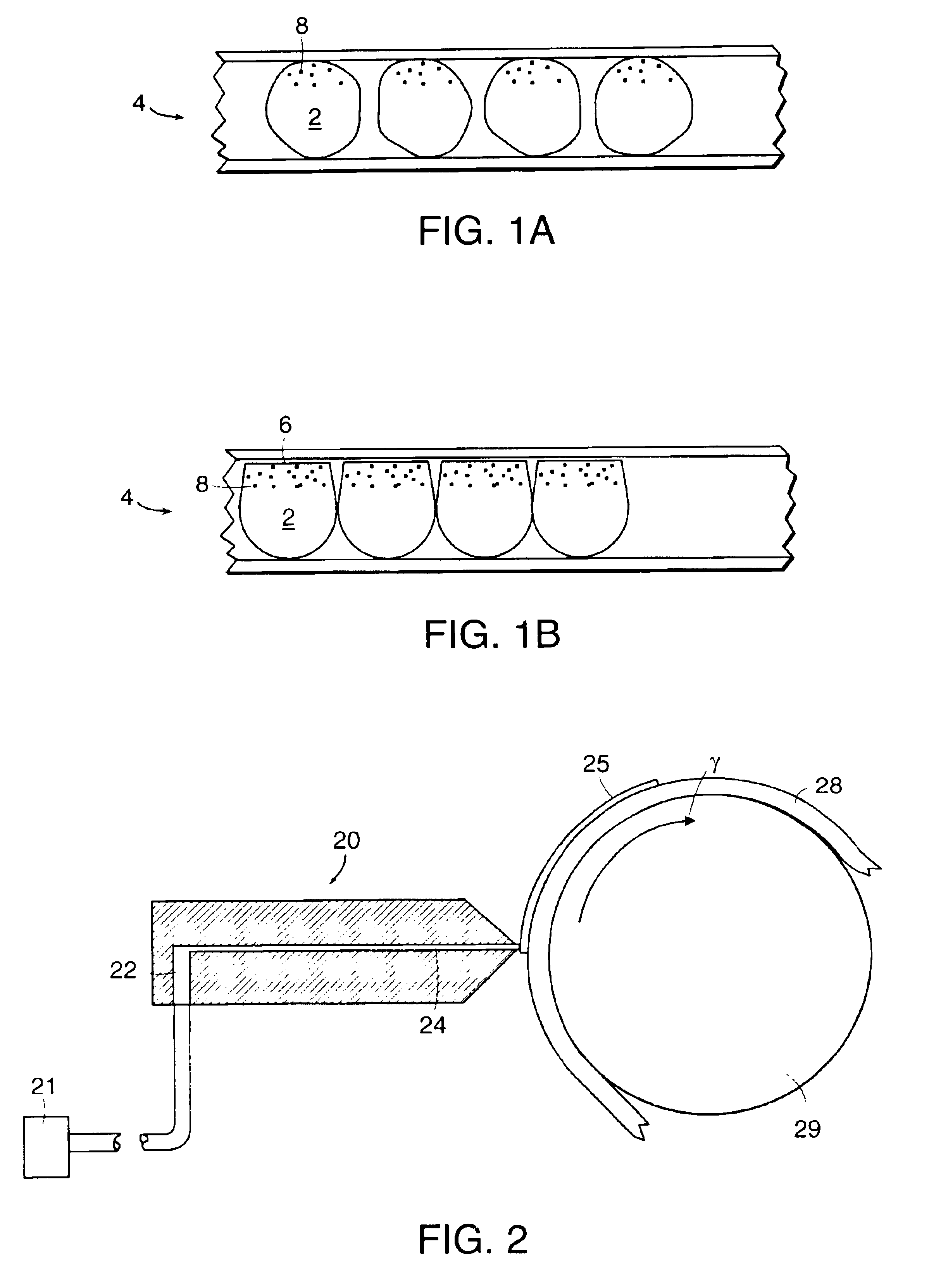
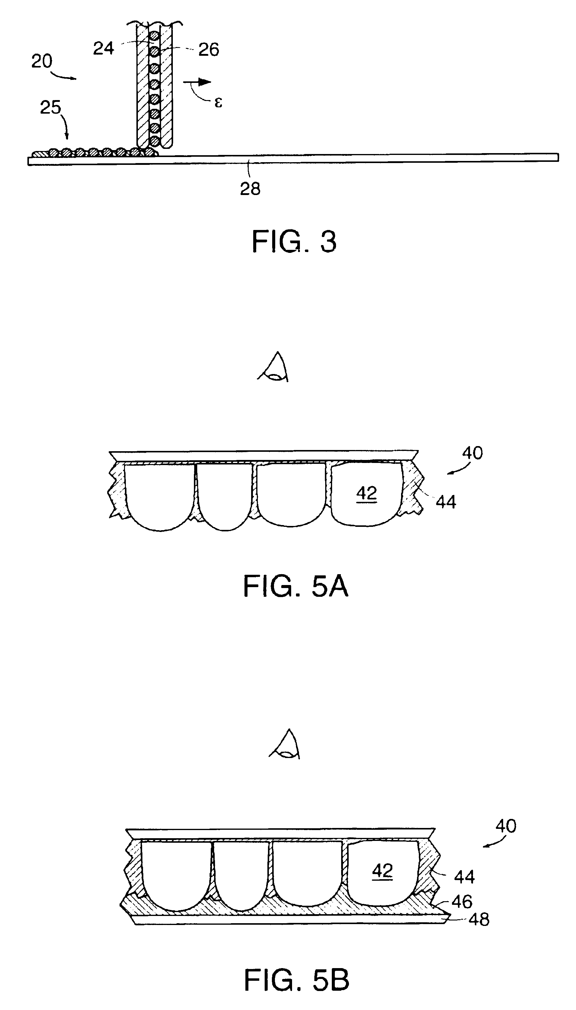
The present invention is directed to a bright, high-contrast encapsulated electrophoretic display. Such a display can be achieved with various materials and methods that allow the display to be constructed such that a monolayer of capsules on a substrate is formed. The capsules contain at least an electrophoretically mobile particle and a suspending fluid. In addition to forming a monolayer, materials and methods of the present invention allow the capsules in the monolayer to pack together and / or deform in certain, useful configurations. For example, capsules can be non-spherical.

Problems solved by technology

Current displays are not capable of achieving uniform brightness or good contrast due to limitations in their construction.

Method used


Image

  • Encapsulated electrophoretic displays having a monolayer of capsules and materials and methods for making the same
  • Encapsulated electrophoretic displays having a monolayer of capsules and materials and methods for making the same
  • Encapsulated electrophoretic displays having a monolayer of capsules and materials and methods for making the same

Examples


example 2

2. EXAMPLE 2

The following is an example of the preparation of microcapsules by in situ polymerization.

In a 500 mL non-baffled jacketed reactor is mixed 50 mL of a 10 wt % aqueous solution of ethylene co-maleic anhydride (Aldrich), 100 mL water, 0.5 g resorcinol (Aldrich), and 5.0 g urea (Aldrich). The mixture is stirred at 200 rpm and the pH adjusted to 3.5 with a 25 wt % NaOH solution over a period of 1 minute. The pH is monitored using a pH meter that was previously calibrated with pH 7.0 and pH 4.0 buffer solutions. To this is slowly added the oil phase, prepared as described above in Ex. 1, and agitation is increased to 450 rpm to reduce the average particle size to less than 200 μm. 12.5 g of a 37 wt % aqueous formaldehyde solution is then added and the temperature raised to 55° C. The solution is heated at 55° C. for two hours.

example 3

3. EXAMPLE 3

The following is an example of the preparation of microcapsules by interfacial polymerization.

To 44 g of the oil phase, prepared as described above in Ex. 1, is added 1.0 g of sebacoyl chloride (Aldrich). Three milliliters of the mixture is then dispersed in 200 mL of water with stirring at 300 rpm at room temperature. To this dispersion is then added 2.5 mL of a 10 wt. % aqueous solution of 1,6-diaminohexane. Capsules form after about one hour.

E. Binder Material

The binder typically is used as an adhesive medium that supports and protects the capsules, as well as binds the electrode materials to the capsule dispersion. A binder can be non-conducting, semiconductive, or conductive. Binders are available in many forms and chemical types. Among these are water-soluble polymers, water-borne polymers, oil-soluble polymers, thermoset and thermoplastic polymers, and radiation-cured polymers.

Among the water-soluble polymers are the various polysaccharides, the polyvinyl alcohols...


PUM

PropertyMeasurementUnit
thicknessaaaaaaaaaa
thicknessaaaaaaaaaa
thicknessaaaaaaaaaa

Abstract

An encapsulated electrophoretic display having a plurality of non-spherical capsules disposed substantially in a single layer on a substrate.

Description

TECHNICAL FIELDThe present invention generally relates to materials and methods for forming a monolayer of capsules for an encapsulated electrophoretic display.BACKGROUND INFORMATIONCurrent electrophoretic display technology produces a display that neither is as bright nor has as much contrast as is desired. Current displays are not capable of achieving uniform brightness or good contrast due to limitations in their construction. Thus, new materials and methods of construction are needed to provide electrophoretic displays with acceptable brightness and contrast.SUMMARY OF THE INVENTIONThe present invention is directed to a bright, high-contrast encapsulated electrophoretic display. Such a display can be achieved with various materials and methods that allow the display to be constructed such that a monolayer of capsules on a substrate is formed. The capsules contain at least an electrophoretically mobile particle and a suspending fluid. In addition to forming a monolayer, materials...

Claims


Application Information

Patent Timeline
Patent Type & Authority Patents(United States)
IPC IPC(8): G02F1/01G02B26/02G02F1/167G06F3/14G04G1/00G04G1/06G06F3/147G09F9/37G09F9/302G02F1/1334G02F1/1333G02F1/13G02F1/16757G04G21/04
CPCG02B26/026G02F1/167G06F3/147G06K19/07703G09F9/302G09F9/372G06F3/1446G02F1/133305G02F1/1334G02F2202/28G09G2380/04G02F1/16757
Inventor ALBERT, JONATHAN D.CROSSLEY, GLENGERAMITA, KATHARINEAMUNDSON, KARL R.STEINER, MICHAEL L.DRZAIC, PAULLOXLEY, ANDREWCOMISKEY, BARRETTVALIANATOS, PETER J.
Owner E INK CORPORATION
Why Eureka
Try Eureka