System and method for positioning an electric portal imaging device

a technology of portal imaging and positioning system, which is applied in the field of radiation emitting devices, can solve the problems of time-consuming and complex process, and achieve the effect of accurate positioning and sufficient clearan

Inactive Publication Date: 2005-01-04
SIEMENS MEDICAL SOLUTIONS USA INC
View PDF8 Cites 61 Cited by
  • Summary
  • Abstract
  • Description
  • Claims
  • Application Information

AI Technical Summary

Benefits of technology

A radiation therapy apparatus according to an embodiment of the present invention includes a portal imaging device having a portal imaging device positioner for accurately positioning the EPID, providing sufficient clearance, and maneuverability across a wide range of motion.

Problems solved by technology

This can be a complex and time-consuming process.

Method used


Image

  • System and method for positioning an electric portal imaging device
  • System and method for positioning an electric portal imaging device
  • System and method for positioning an electric portal imaging device

Examples


Embodiment Construction

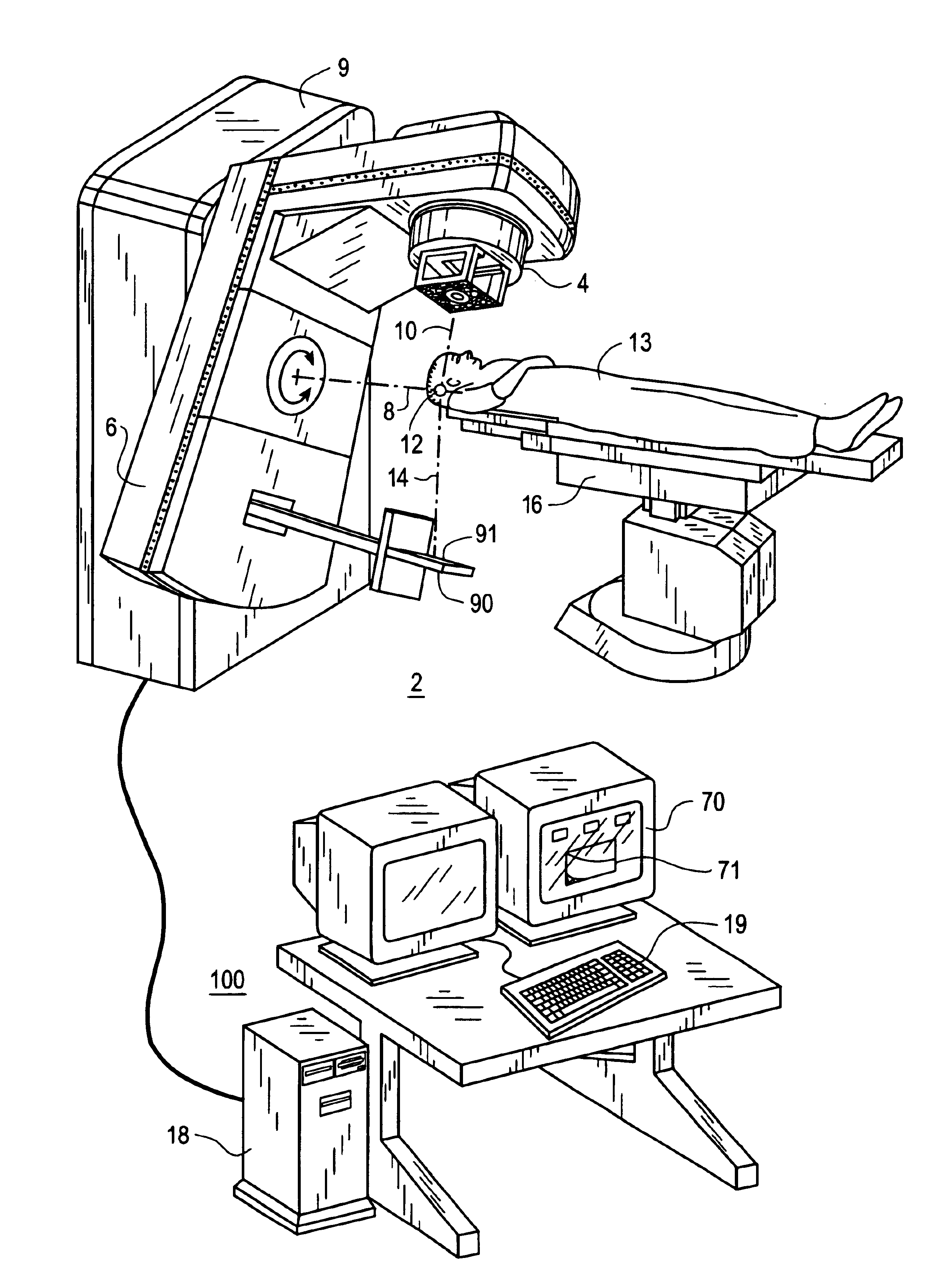
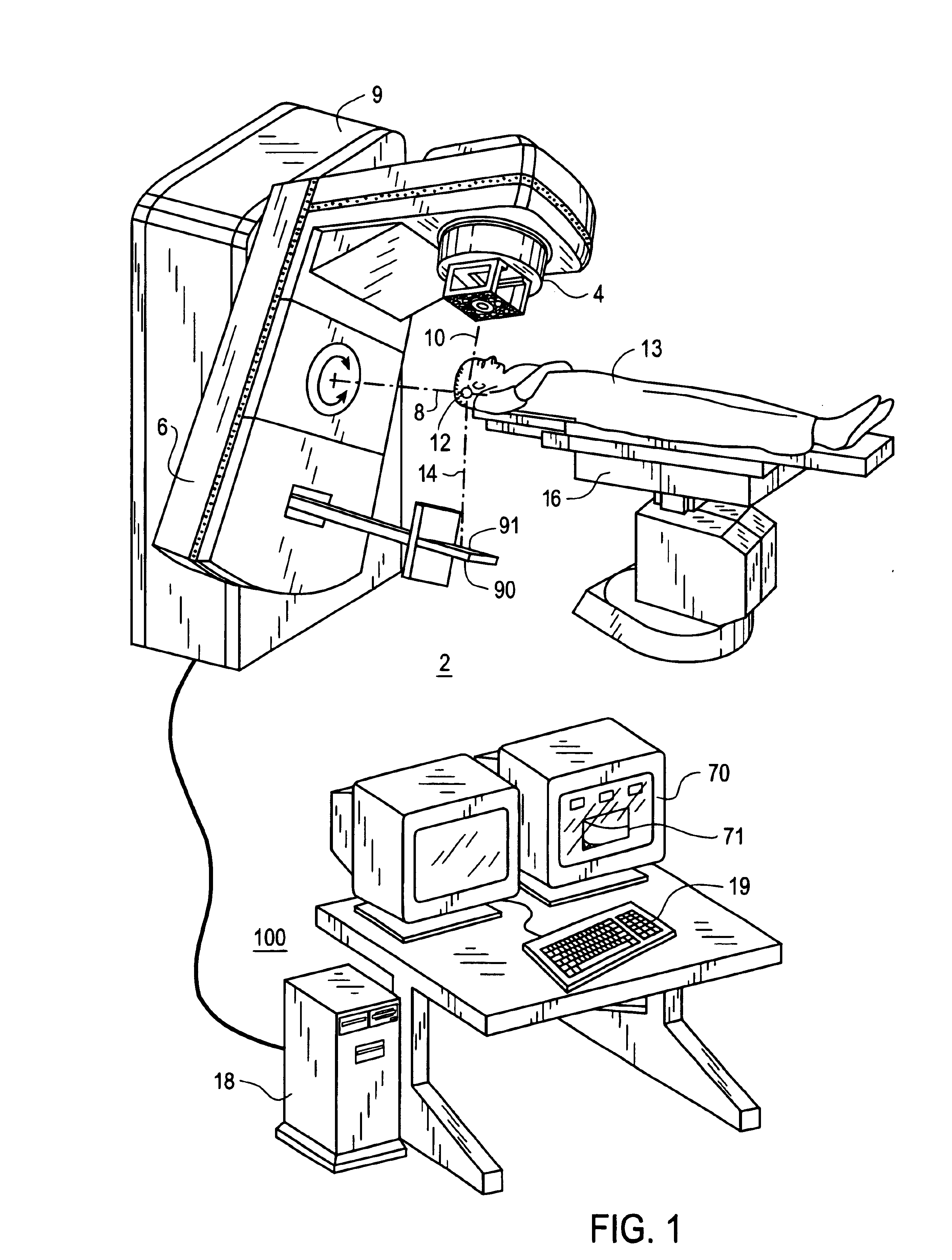
Turning now to the drawings and, with particular attention to FIG. 1, a radiation treatment apparatus embodying the present invention is shown therein and generally identified by reference numeral 2. The radiation treatment apparatus 2 includes a beam shielding device (not shown) within a treatment head 4, a control unit in a housing 9 and a treatment unit 100. The radiation treatment device 2 includes a gantry 6 which can be swiveled around a horizontal axis of rotation 8 in the course of a therapeutic treatment. The treatment head 4 is fastened to projection of the gantry 6. A linear accelerator is located in the gantry 6 to generate the high powered radiation required for the therapy. The axis of the radiation beam emitted from the linear accelerator and the gantry 6 is designated by 10. Electron or photon radiation can be used for the therapy.

During the treatment, the radiation beam is trained on a zone 12 of an object 13, for example, a patient who is to be treated and who lies...


PUM


Abstract

A portal imaging device positioning apparatus includes a portal imaging device positioner (255) attachable to a support (256). The portal imaging device positioner (255) is adapted to vertically adjust an imaging panel (250) in a treatment or dosimetry mode to receive radiation through a body in the patient plane (8a), and adjust the panel in a physics mode to receive radiation at the patient plane (8a).

Description

BACKGROUND OF THE INVENTIONThe present invention relates to a radiation emitting device, and more particularly, to a system and method for evaluating beam quality during therapy using electronic portal imaging.DESCRIPTION OF THE RELATED ARTRadiation emitting devices are generally known and used, for instance, as radiation therapy devices for the treatment of patients. A radiation therapy device generally includes a gantry which can be swiveled around a horizontal axis of rotation in the course of a therapeutic treatment. A linear accelerator is located in the gantry for generating a high energy radiation beam for therapy. This high energy radiation beam can be an electron beam or photon (X-ray) beam. During treatment, this radiation beam is trained on one zone of a patient lying in the isocenter of the gantry rotation.Prior to receiving therapeutic doses of radiation, the patient must be positioned accurately and precisely. Radio-therapists have historically used laser pointers and ...

Claims


Application Information

Patent Timeline
Patent Type & Authority Patents(United States)
IPC IPC(8): A61B6/00A61N5/10
CPCA61B6/4233A61B6/4441A61N5/1049A61B6/467A61N2005/1054A61B6/469
Inventor CLARK, CHARLESLENTZ, LORENPENNY, DEBRAGIBB, WILLIAM J.STEINBERG, TODD H.
Owner SIEMENS MEDICAL SOLUTIONS USA INC
Why Eureka
Try Eureka