Exhaust emission control system for internal combustion engine

a technology of exhaust emission control and internal combustion engine, which is applied in the direction of testing/calibration apparatus, digital computer details, special data processing applications, etc., can solve the problem that the determination of the deterioration of the nox removal device cannot be accurately performed

Inactive Publication Date: 2005-01-04
HONDA MOTOR CO LTD
View PDF14 Cites 34 Cited by
  • Summary
  • Abstract
  • Description
  • Claims
  • Application Information

AI Technical Summary

Benefits of technology

It is accordingly an object of the present invention to provide an exhaust emission control system which can determine a condition where the SOx concentration in the vicinity of each oxygen concentration sensor is high.

Problems solved by technology

Accordingly, when the concentration of SOx in the vicinity of each oxygen concentration sensor is high, there is a case that the deterioration determination of the NOx removing device cannot be accurately performed.

Method used


Image

  • Exhaust emission control system for internal combustion engine
  • Exhaust emission control system for internal combustion engine
  • Exhaust emission control system for internal combustion engine

Examples


second preferred embodiment

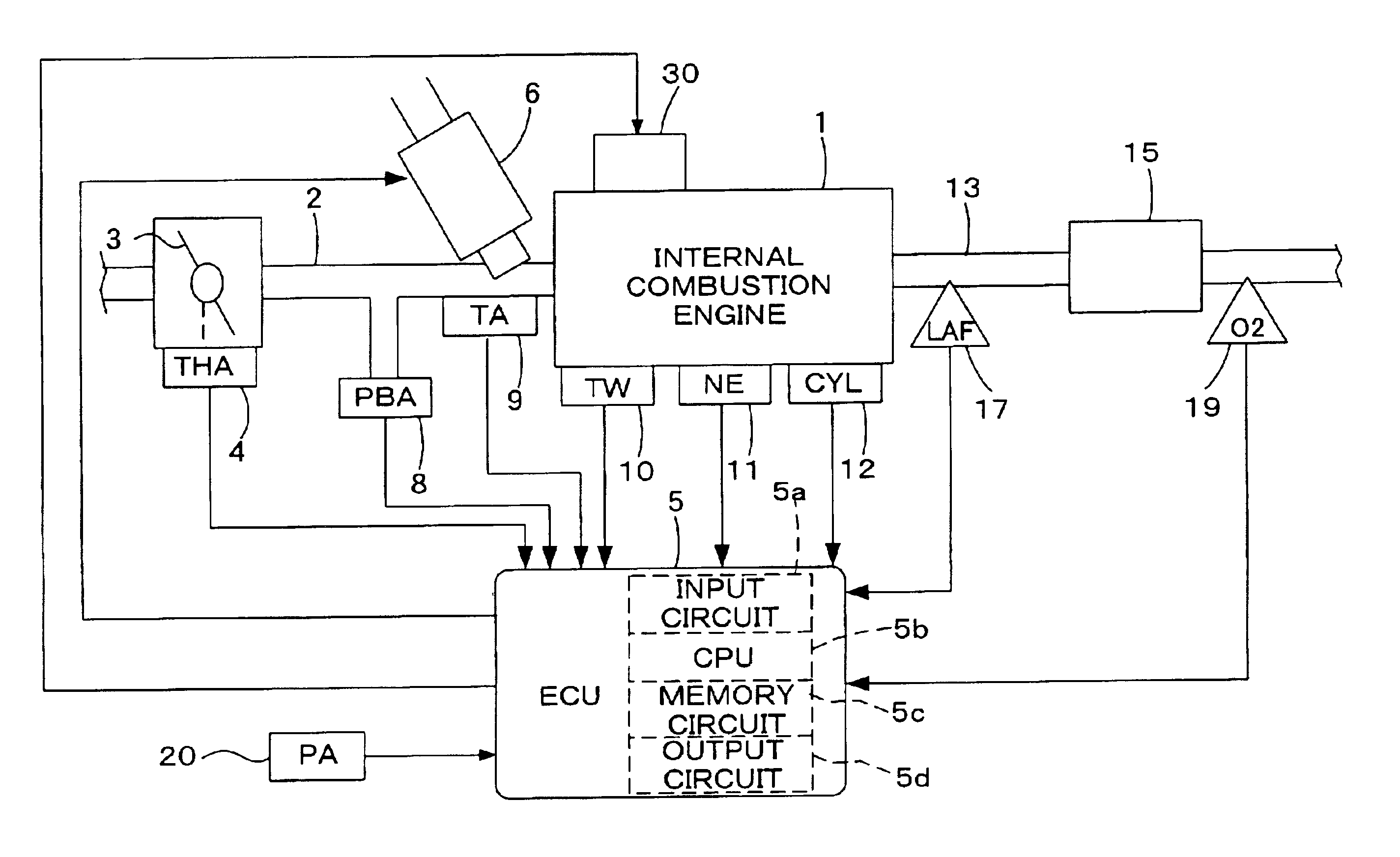
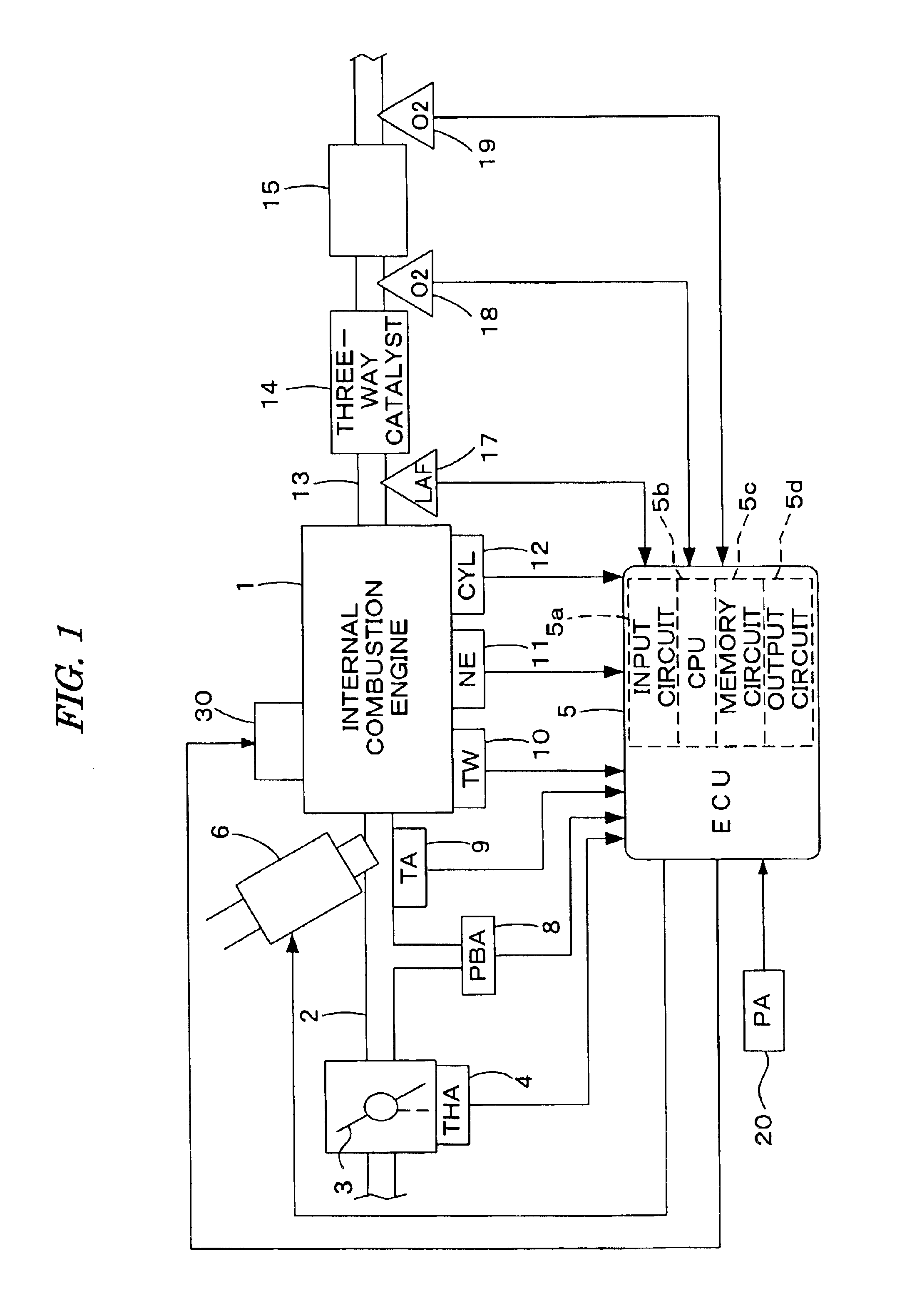
FIG. 16 is a schematic diagram showing the configuration of an internal combustion engine and a control system therefor, including an exhaust emission control system according to a second preferred embodiment of the present invention. The configuration shown in FIG. 16 is different from the configuration of the first preferred embodiment shown in FIG. 1 in the point that the three-way catalyst 14 and the upstream O2 sensor 18 are not provided in the exhaust pipe 13. The second preferred embodiment is similar to the first preferred embodiment except the following aspects.

In this preferred embodiment, the SOx concentration determination is performed according to the output LVO2 from the downstream O2 sensor 19. That is, the process of FIG. 6 is executed by using the downstream O2 sensor output LVO2 instead of the upstream O2 sensor output SVO2 to perform the SOx concentration determination.

Further, the deterioration determination for the NOx removing device 15 is executed according to...


PUM

PropertyMeasurementUnit
crank angleaaaaaaaaaa
atmospheric pressureaaaaaaaaaa
timeaaaaaaaaaa

Abstract

An exhaust emission control system for an internal combustion engine is disclosed. The system includes a NOx removing device provided in an exhaust system of the engine for removing NOx contained in exhaust gases, and an oxygen concentration sensor provided in the exhaust system. The air-fuel ratio of the air-fuel mixture to be supplied to the engine is changed from a value which is leaner than the stoichiometric ratio to a value which is richer than the stoichiometric ratio. It is determined whether or not a sulfur oxide concentration in the exhaust gases is high according to a transient characteristic of an oxygen concentration detected by the oxygen concentration sensor after the air-fuel ratio is changed.

Description

BACKGROUND OF THE INVENTIONThe present invention relates to an exhaust emission control system for an internal combustion engine, and more particularly to such an exhaust emission control system having a function of monitoring the concentration of sulfur oxide (SOx) contained in exhaust gases.Conventionally known is a technique for removing NOx (nitrogen oxide) contained in exhaust gases by providing a NOx removing device including a NOx absorbent in an exhaust system of an internal combustion engine. Further, a technique of determining a degree of deterioration of the NOx removing device is known in the art (Japanese Patent Laid-open No. Hei 10-299460). In this technique, two oxygen concentration sensors are arranged upstream and downstream of the NOx removing device, and the air-fuel ratio of an air-fuel mixture to be supplied to the engine is changed from a lean region to a rich region with respect to the stoichiometric ratio. Then, the degree of deterioration of the NOx removing...

Claims


Application Information

Patent Timeline
Patent Type & Authority Patents(United States)
IPC IPC(8): F01N11/00F01N3/08F02D41/02F02D45/00F01N3/20F01N3/22F01N3/28F02D13/02F02D41/04F02D41/14
CPCF01N3/101F01N11/007F02D41/028F01N3/0842F01N2550/02Y10T477/663F01N2900/0422Y02T10/47Y02T10/22F01N2550/03Y02T10/12Y02T10/40
Inventor MOTEKI, NORIOMIYASHITA, KOTAROTANABE, YUICHIROHASHIZUME, MITSUOHASUMI, HIROAKI
Owner HONDA MOTOR CO LTD
Why Eureka
Try Eureka