Real-time monitoring system for codec-effect sampling during digital processing of a sound source

Inactive Publication Date: 2005-01-04
AVID TECHNOLOGY
View PDF3 Cites 0 Cited by
  • Summary
  • Abstract
  • Description
  • Claims
  • Application Information

AI Technical Summary

Benefits of technology

Now, for the first time, a method allowing a user, during the process of making a digital recording, to simultaneously monitor the sound being recorded, perceiving it as it would sound in its final form after compression and decompression is provided. By utilizing such an improved method a user can eliminate many cumbersome steps in determining compression / decompression effects, thus making more efficient use of recording time and resources.

Problems solved by technology

However, depending on the type of signal source and compression / decompression techniques utilized, some adverse affects on data can occur during the process, sometimes causing modifications to the resulting sound.
To ensure data integrity, every compression algorithm must have a matching decompression algorithm, and because compression reduces data density as previously described, a problem is presented in that the resulting sound is almost always invariably affected to some degree.
For example, a compression / decompression algorithm that creates only a small change to the resulting sound in terms of percent of total harmonic distortion, for instance, may cause the created sound, in its final form, to have undesirable audible characteristics when played back.
A problem is presented by this method however, since during the recording process, a user wishing to listen to the digital recording must first stop recording and then go into a playback mode at which point the compression algorithm being used during recording is replaced with a decompression algorithm, thus allowing playback of recording.
Such a method can require multiple, sometimes inconvenient and disruptive steps resulting in a cumbersome overall process for many users.

Method used


Image

  • Real-time monitoring system for codec-effect sampling during digital processing of a sound source
  • Real-time monitoring system for codec-effect sampling during digital processing of a sound source
  • Real-time monitoring system for codec-effect sampling during digital processing of a sound source

Examples


Embodiment Construction

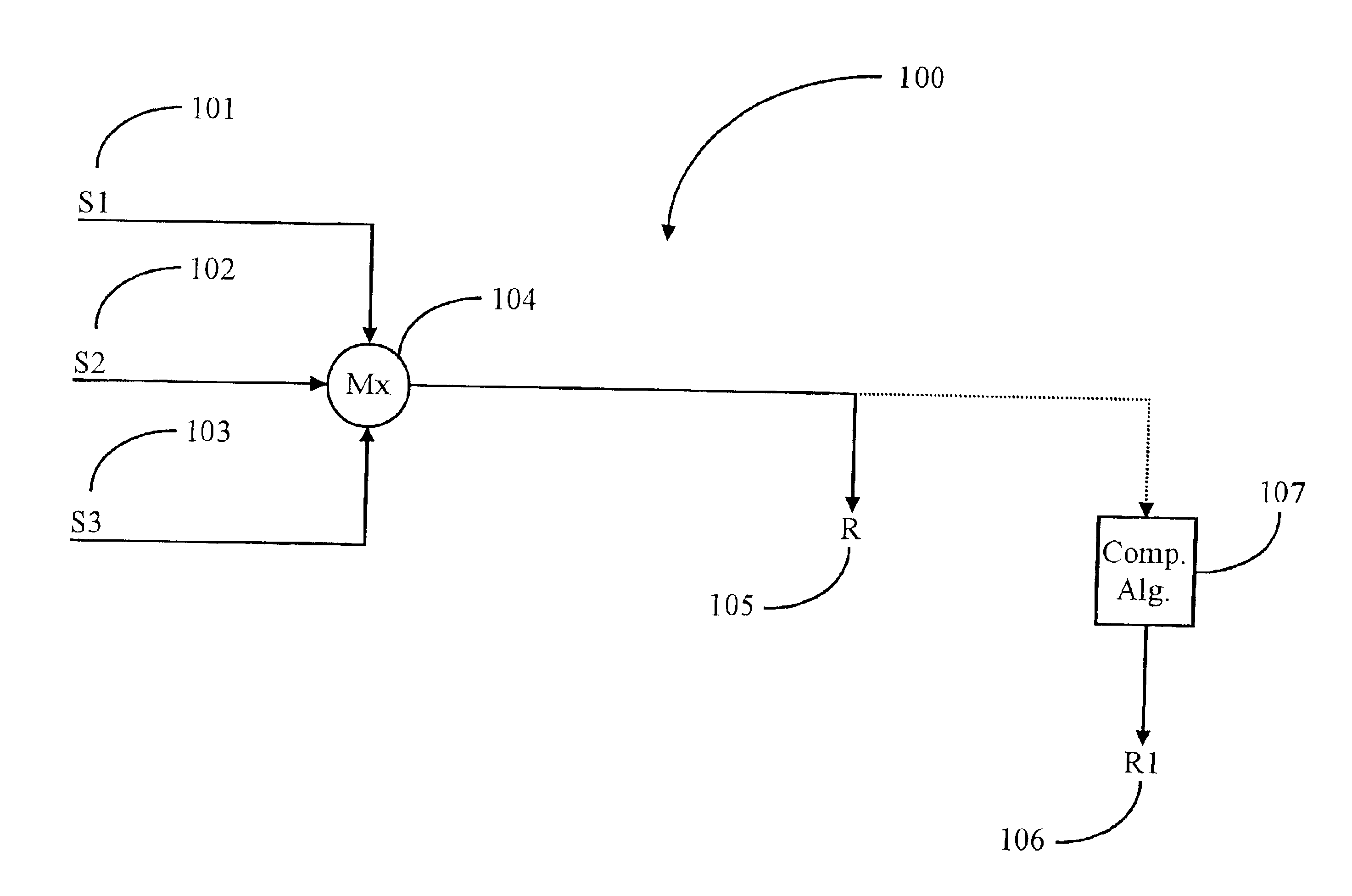
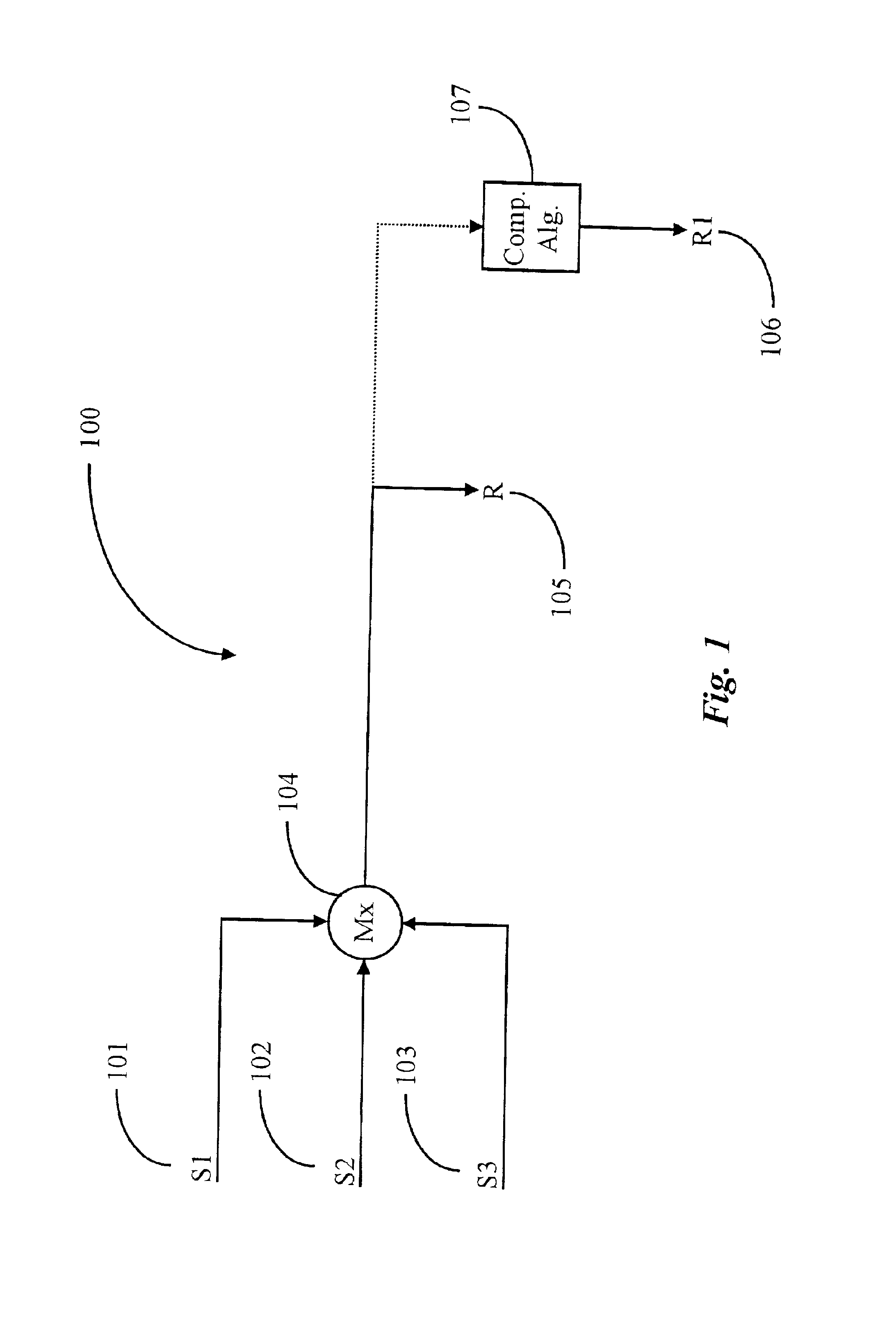
As previously described, a typical digital recording and mixing system consists of many separate functional units including an apparatus for changing signal strength and characteristics, signals incoming from usually more than one signal or sound source, a digital recording apparatus for processing and saving of digital signals, and an apparatus enabling playback of the digital recording.

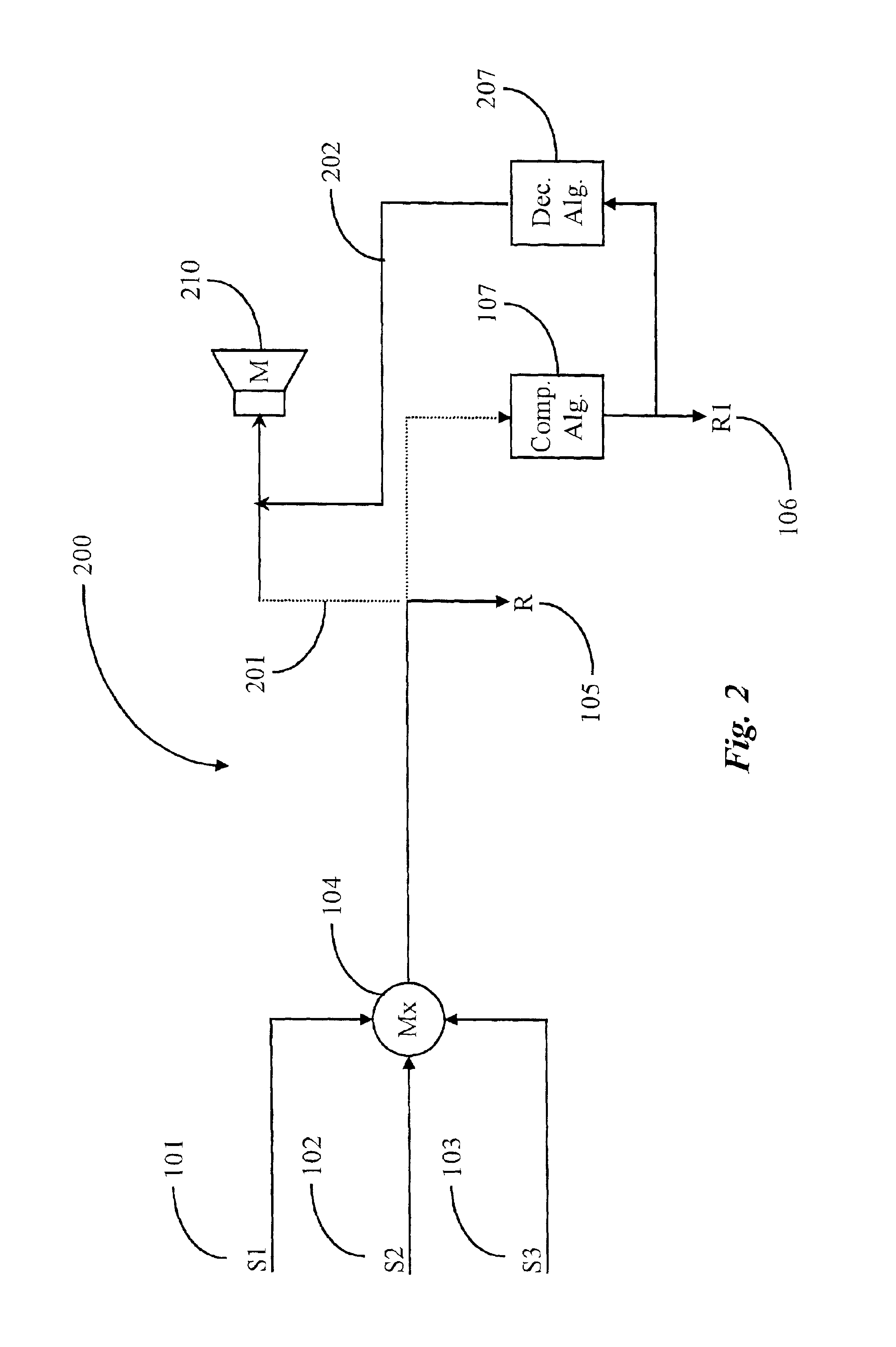
FIG. 1 is a simplified block diagram of a typical recording and mixing system according to conventional art. For reasons of clarity and simplicity, elements of FIG. 1 are represented only by simple block characters without details of their specific operations. System 100 is shown in this example having a plurality of sound or signal inputs, typical of mixing and recording systems known in the art, represented as source S1101, source S2102, and source S3103. Signal sources such as described in a typical system are mixed in a signal mixing console such as mixer Mx 104 allowing the user to establish lo...


PUM


Abstract

A digital processing system for monitoring sound effects produced by codecs during a signal processing session is provided. The digital processing system comprises, a sound source for producing signals for processing, a sound monitor having at least two channels for monitoring sound quality of the sound source, a sound recorder for recording the sound source, a playback device for playing a recorded file of sound produced by the sound source, a codec simulator for simulating sound effects produced by codecs, a plurality of codecs for compressing and decompressing sound files and a control interface for sampling, adjusting, and implementing an optimum codec based on monitoring of sound effects produced by codec simulation. A user controlling the system may monitor sound variances produced by any one of the plurality of codecs affecting the quality of sound from the sound source during signal processing of the source sound without interruption of the signal-processing session.

Description

FIELD OF THE INVENTIONThe present invention is in the field of digital signal processing and pertains more particularly to methods and apparatus for real-time user monitoring.BACKGROUND OF THE INVENTIONThe technology pertaining to sound recording and reproduction originated late in the 19th century with several key inventions beginning with simple energy transforming devices and later including such devices as simple photographs, and development of the vacuum tube enabling electrical impulse amplification. Recent technology has incorporated the use of magnetic tape, digital data recording, and advanced digital signal processing. Such modern digital processing and recording techniques have more recently been integrated into a large segment of the music recording industry, enabling those skilled in the art, such as sound engineers or technicians using digital signal processing, to shape the final sound qualities of a signal source such as a musical instrument for example. Modern digit...

Claims


Application Information

Patent Timeline
IPC IPC(8): G10L19/00
CPCG10L25/69
Inventor SILFVAST, ROBERT DENTONCAMPBELL, PHILIP J. E.SILFVAST, SCOTTIZSAK, ANDORDEBENEDICTIS, PAULMILNE, STEVEN H.
Owner AVID TECHNOLOGY
Why Eureka
Try Eureka